Method for producing absolute zero-position alignment marks by semi-reflective zero-position grating

A zero grating and alignment mark technology, applied in the field of measurement and metrology, can solve the problem that the transmission zero grating cannot be applied to the equipment mechanism

Inactive Publication Date: 2007-03-07
UNIV OF SCI & TECH OF CHINA
View PDF0 Cites 8 Cited by
  • Summary
  • Abstract
  • Description
  • Claims
  • Application Information

AI Technical Summary

Problems solved by technology

The above encoding method can be applied to transmission type one-dimensional and two-dimensional zero position grating; however, due to structural limitations, transmission type zero position grating cannot be applied to some equipment mechanisms, such as photolithography machines

Method used


Image

  • Method for producing absolute zero-position alignment marks by semi-reflective zero-position grating
  • Method for producing absolute zero-position alignment marks by semi-reflective zero-position grating
  • Method for producing absolute zero-position alignment marks by semi-reflective zero-position grating

Examples


Embodiment 1

[0018] Example 1: Generating an absolute zero alignment mark through a transflective zero grating

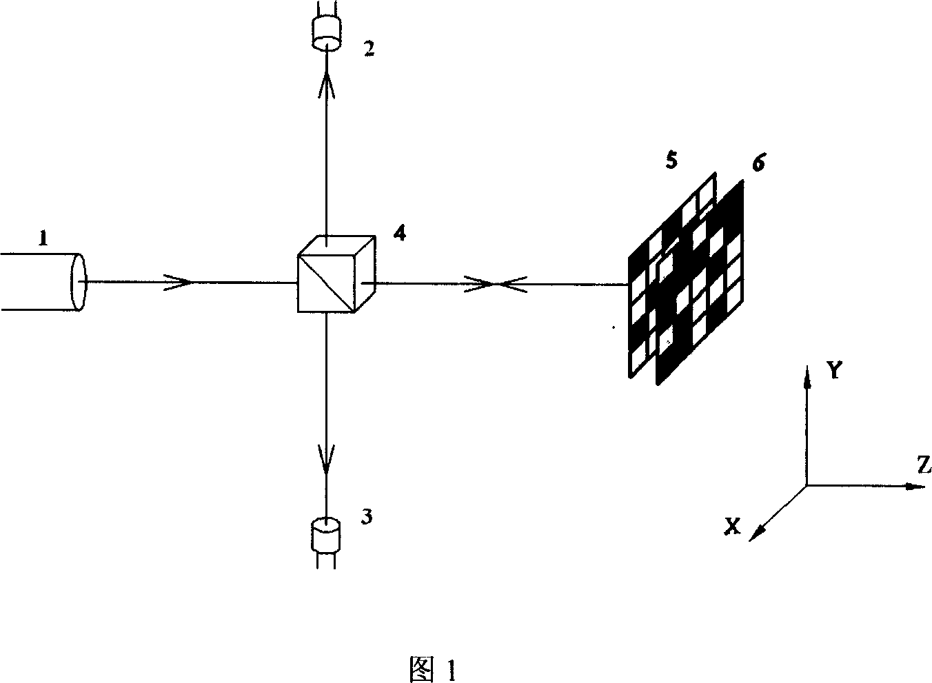
[0019] Figure 1 shows a schematic diagram of the structure of a transflective two-dimensional zero grating system: the coordinates Y and Z are perpendicular to each other. The parallel light source 1 passes through the beam-splitting prism 4 vertically, and the working surface of the beam-splitting prism 4 is parallel to the X-Y plane. After beam-splitting, the first optical axis passes through the beam-splitting prism 4 and propagates along the Z direction, and the second optical axis passes through the beam-splitting prism 4 The reflection propagates along the negative direction of the coordinate Y; a photoelectric receiver 3 is placed on the second optical axis, which is used to judge the intensity change of the light source and compensate the final result; the transmission grating 5 is installed behind the beam splitting prism 4, and the first The optical axis is perpendicul...

Embodiment 2

[0025] Example 2: Application of transflective alignment technology in photolithography machine

[0026] The transflective method can be used as a lithography alignment technology for the alignment of the mask and the silicon wafer in the lithography machine.

[0027] Select the grating with the corresponding grid constant according to the alignment accuracy requirements, make the transmission grating on the mask, and make the reflective grating on the silicon wafer. To align the mask with the silicon wafer in the lithography machine, the mask must be aligned. Combine with the silicon chip as follows: first place the mask perpendicular to the incident light path, then install the silicon chip on a plane parallel to the plane where the mask is located, and perpendicular to the incident light path; adjust the relative position of the mask and the silicon chip so that The two gratings made on them are completely aligned, and then the distance between the two is adjusted to obtain...


PUM


Abstract

This invention relates to one method by use of transmission grating to generate zero calibration mark, which adopts two blocks of grating with special coding zero mark an comprises the following steps: putting the grating on z direction and beam goes vertical to the grating; then fixing the reflection grating on the back of transmission grating along z direction parallel to the transmission grating and is reflected back and making two gratings calibrate through adjusting reflection grating angle and position to get the absolute zero position in X-Y plane; adding split prism on the light path to set photoelectricity receiver to receive light signal for judging and reading.

Description

Technical field: [0001] The invention belongs to the technical field of measurement and metrology, and in particular relates to a method for generating an absolute zero alignment mark through a transflective zero grating used in the photolithography alignment technology of a photolithography machine. Background technique: [0002] From the early 1960s to the present, lithography alignment technology has developed from the initial bright field and dark field alignment to today's interference holography or heterodyne interference holography alignment technology and mixed matching and rough and fine alignment technology. The quasi-precision is improved from the original micron level to the nanometer level, which promotes the development of integrated circuits. my country's "Research Progress in Lithography Alignment Technology" (No. 117, 2004, pages 30 to 34) reviewed the development and function of lithography alignment technology, and analyzed and evaluated the principles and...

Claims


Application Information

Patent Timeline
Patent Type & Authority Applications(China)
IPC IPC(8): G03F9/00G03F7/20H01L21/00
Inventor 黄文浩叶锡标周成刚
Owner UNIV OF SCI & TECH OF CHINA
Why Eureka
Try Eureka