Heat recovery combustion furnace

A heat recovery type, combustion furnace technology, applied in the combustion method, combustion type, incinerator and other directions, can solve the problems of air pollution, VOC waste gas residue, control errors, etc., to reduce air pollution, low manufacturing cost, and simple production. Effect

Inactive Publication Date: 2007-03-14
SUPERIOR AIR TREATMENT TECH
View PDF0 Cites 4 Cited by
  • Summary
  • Abstract
  • Description
  • Claims
  • Application Information

AI Technical Summary

Problems solved by technology

[0007] However, when the heat recovery chamber 12 is in the air intake mode, VOC exhaust gas enters the combustion chamber 16 from the heat recovery chamber 12, but due to the gas pressure, the VOC exhaust gas in the heat recovery chamber 12 cannot completely enter the combustion chamber 16, thus making Part of the VOC exhaust gas will remain in the empty chamber 12b
In this way, when the heat recovery chamber 12 is in the exhaust mode, clean gas will enter the heat recovery chamber 12 from the combustion chamber 16, and then be discharged into the atmosphere by the exhaust manifold 26, while remaining in the empty chamber 12b VOC waste gas will be discharged into the atmosphere together with clean gas, causing air pollution
In addition, the conventional heat recovery furnace 10 utilizes four independent valves 20a, 20b, 22a and 22b to control the gas in and out of the heat recovery chambers 12 and 14, that is, when the conventional heat recovery furnace 10 When reacting, it must control four valves 20a, 20b, 22a and 22b at the same time, but the more the number of valves, the more complicated the valve control program, and the easier it is to generate control errors, thereby reducing the heat recovery type combustion furnace 10. waste gas treatment efficiency

Method used


Image

  • Heat recovery combustion furnace
  • Heat recovery combustion furnace
  • Heat recovery combustion furnace

Examples


Embodiment Construction

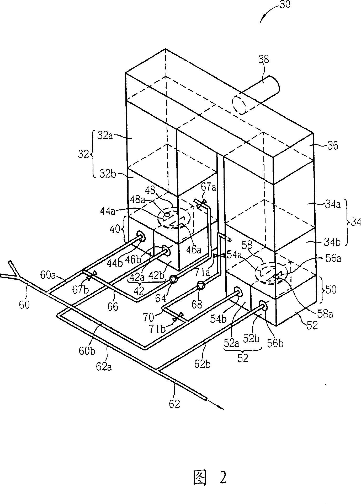
[0056] Please refer to FIG. 2 to FIG. 4 . FIG. 2 to FIG. 4 are schematic diagrams of a heat recovery combustion furnace according to a preferred embodiment of the present invention. As shown in FIG. 2 , a heat recovery combustion furnace 30 includes a heat recovery chamber 32 , a heat recovery chamber 34 , and a combustion chamber 36 connected between the heat recovery chamber 32 and the heat recovery chamber 34 . Wherein, the heat recovery chamber 32 includes a regenerator 32a and an empty chamber 32b below the regenerator 32a, and the heat recovery chamber 34 also includes a regenerator 34a and an empty chamber below the regenerator 34a. 34b, the heat storage chambers 32a and 34a are filled with a plurality of heat storage bricks, and the heat storage bricks are usually made of heat storage materials such as stone or ceramics. In addition, a burner 38 is provided in the combustion chamber 36 to maintain the combustion chamber 36 at an appropriate reaction temperature (800° C...


PUM


Abstract

The invention provides a heat-recovery burnout oven, comprising combustion chamber for combusting gas, two heat-recovery rooms connected with two ends of combustion chamber respectively, two switching valves connected with said heat recovery rooms respectively and at least one disposing device for redundant gas for cleaning the residue gas in every heat recovery rooms. Every switching valves switch inlet and outlet of the valve by rotary table with one groove so that the operation is simple.

Description

technical field [0001] The present invention relates to a heat recovery type burner (Regenerative Thermal Oxidizer, RTO), in particular to a heat recovery type burner with a switching valve with simple control. Background technique [0002] The heat recovery combustion furnace is an energy-saving and environmental protection device used to treat low-concentration organic volatile gases (volatile organic compounds, VOC), and because the heat recovery combustion furnace has high heat utilization efficiency (>90%) and fuel consumption Due to the advantages of low energy consumption, heat recovery combustion furnaces have been widely used in various industries, such as semiconductor industry, optoelectronic industry, oil refining and petrochemical, synthetic resin manufacturing, and surface coating industries. [0003] Please refer to FIG. 1 , which is a schematic diagram of a traditional heat recovery combustion furnace. As shown in FIG. 1 , a heat recovery combustion furna...

Claims


Application Information

Patent Timeline
Patent Type & Authority Applications(China)
IPC IPC(8): F23G7/06F23G5/46
Inventor 廖国良张正煌彭宏达
Owner SUPERIOR AIR TREATMENT TECH
Why Eureka
Try Eureka