Bidirectional optical receiving-transmitting secondary module
A sub-module, two-way optical technology, applied in electromagnetic transceivers, coupling of optical waveguides, electromagnetic wave transmission systems, etc., can solve the problems of filter 24 displacement, optical component interference, optical signal leakage, etc. Efficiency, increased reliability, reduced number of effects
- Summary
- Abstract
- Description
- Claims
- Application Information
AI Technical Summary
Problems solved by technology
Method used
Image
Examples
Embodiment 1
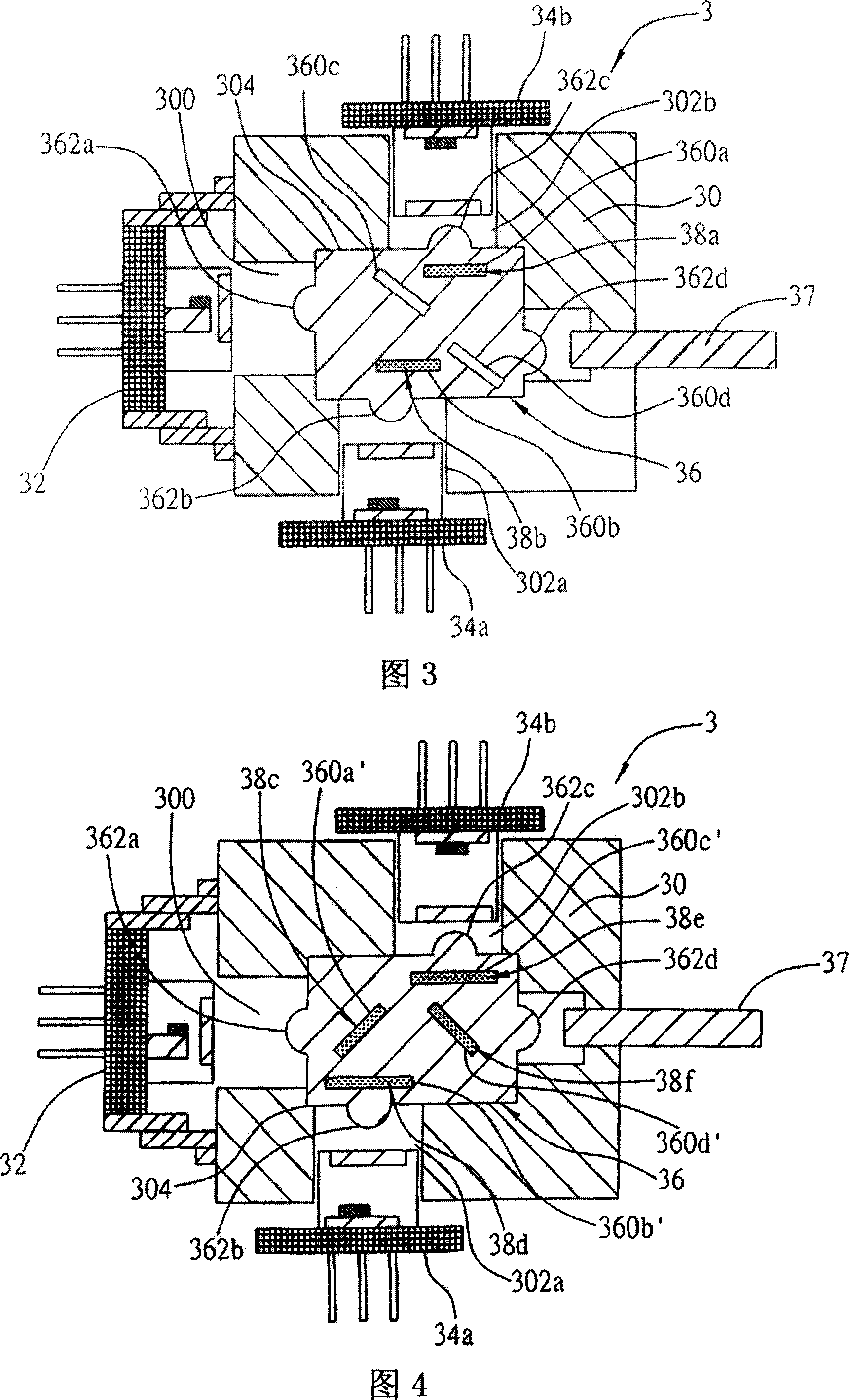
[0024] Fig. 3 is a sectional view of Embodiment 1 of the present invention. As shown in the figure, the bidirectional optical transceiver sub-module 3 of the present invention includes a housing body 30 and a housing space 304 . Wherein, the receiving body 30 has inside: a first opening 300 for connecting the light-emitting element 32 ; second openings 302 a and 302 b for connecting the light-receiving elements 34 a and 34 b respectively;
[0025] Wherein, the light-emitting element 32 in the first embodiment is used to send an optical signal to the light-conducting element 37 . Wherein, the light emitting element 32 is a laser diode (LD, Laser Diode), and the light conducting element 37 is an optical fiber.
[0026] The light receiving elements 34 a and 34 b are used to receive the light signal transmitted from the light conducting element 37 .
[0027] The carrier 36 is made of a light-transmitting material and has four grooves 360a, 360b, 360c and 360d, and the groove 360...
Embodiment 2
[0031] Fig. 4 is a sectional view of Embodiment 2 of the present invention. Compared with Embodiment 1, the four grooves 360a', 360b', 360c' and 360d' of the carrier 36 are all combined with filters 38c, 38d, 38e and 38f. According to the general optical principle, this embodiment Example 2 can also achieve the same effect as that of Embodiment 1 of the present invention, and its optical signal transmission path is shown in Figure 5A and Figure 5B, wherein Figure 5A shows the transmission path of the light signal sent by the light emitting element 32, and Figure 5B shows the light transmission element The conduction path of the optical signal output by 37, the function of the components shown in Figure 5A and Figure 5B, the detailed implementation and the optical signal transmission mode can be easily deduced from the embodiment 1 and the optical principle.
[0032] Fig. 6 is an exploded perspective view of Embodiment 2 of the present invention. It can be seen from the figure...
PUM
 Abstract
Description
Claims
Application Information
 - R&D
- Intellectual Property
- Life Sciences
- Materials
- Tech Scout
- Unparalleled Data Quality
- Higher Quality Content
- 60% Fewer Hallucinations
Browse by: Latest US Patents, China's latest patents, Technical Efficacy Thesaurus, Application Domain, Technology Topic, Popular Technical Reports.
© 2025 PatSnap. All rights reserved.Legal|Privacy policy|Modern Slavery Act Transparency Statement|Sitemap|About US| Contact US: help@patsnap.com


