Multilayer optical fiber coupler

Inactive Publication Date: 2008-07-01
JIAN BENJAMIN
View PDF27 Cites 8 Cited by
  • Summary
  • Abstract
  • Description
  • Claims
  • Application Information

AI Technical Summary

Benefits of technology

[0014]In order to provide precise, passive alignment of the optical fiber within the fiber socket, the fiber socket is formed to be only slightly larger than the fiber diameter. Single-crystal silicon is particularly useful to form the fiber sockets because silicon DRIE techniques have been developed recently as a result of advances in microelectromechanical system (MEMS) research, which allow vertical holes to be etched at high speeds (up to 10 micron/minute at present) with less than 1 micron vertical variation in hole diameter (i.e. ±0.5 micron). In one embodiment, the deep-etching process uses high definition photolithography and an appropriate high etch selectivity mask to create precisely-dimensioned fiber sockets. These fiber sockets then receive precisely-dimensioned optical fibers, thereby accurately aligning the optical fibers within the fiber socket. The fibers are held in place by epoxy or another suitable adhesive.
[0015]In one embodiment the second layer comprises borosilicate glass such as PYREX, which is advantageous for several reasons. The glass can be strongly and conveniently bonded to silicon by anodic bonding, which is a dry bonding process. The thermal expansion coefficient of borosilicate glass matches well with that of silicon, which provides a durable and reliable structure. Furthermore, the index of refraction of borosilicate glass approximately matches the index of refraction of the core of the optical fiber, which is the light transmitting section of the fiber, and therefore an optical epox

Problems solved by technology
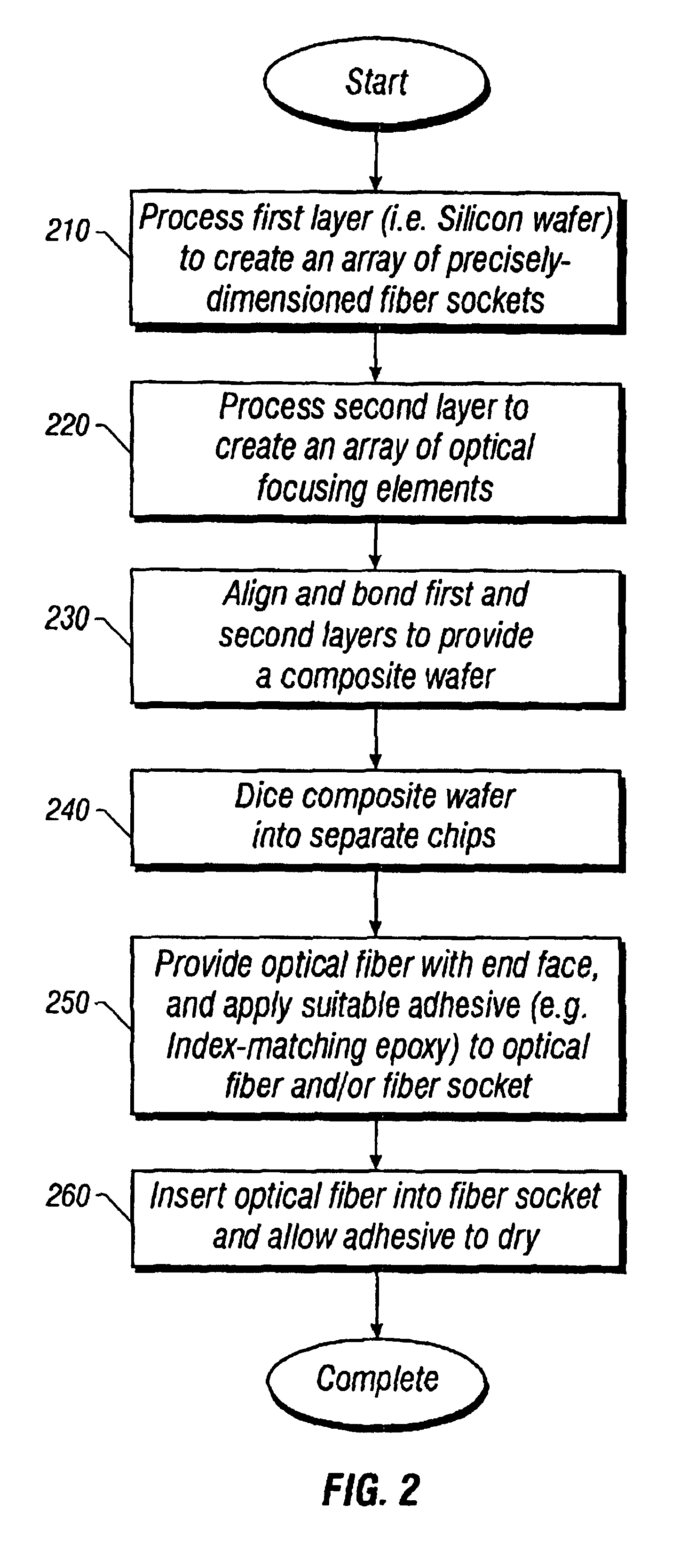
For effective coupling, light must be directed within a cone of acceptance angle and inside the core of an optical fiber; however, any light incident upon the surrounding cladding or outside of the acceptance angle will not be effectively coupled into the optical fiber.
It is a difficult task to couple light into the central core of an optical fiber due to its small size and acceptance angle, particularly if the optical fiber is a single mode optical fiber.
This manual assembly procedure is time consuming, labor intensive, and expensive.
The high cost of aligning optical fiber presents a large technological barrier to cost reduction and widespread deployment of optical fiber modules.
For example, in a splice connection between two optical fibers, a larg

Method used


Image

  • Multilayer optical fiber coupler
  • Multilayer optical fiber coupler
  • Multilayer optical fiber coupler

Examples


Example

[0035]This invention is described in the following description with reference to the Figures, in which like numbers represent the same or similar elements.

Overview

[0036]As discussed in the background section, some single-mode fibers are constructed with very close tolerances. The highly precise diameter of the optical fiber is useful when a precision etched hole is designed to match it, as described herein.

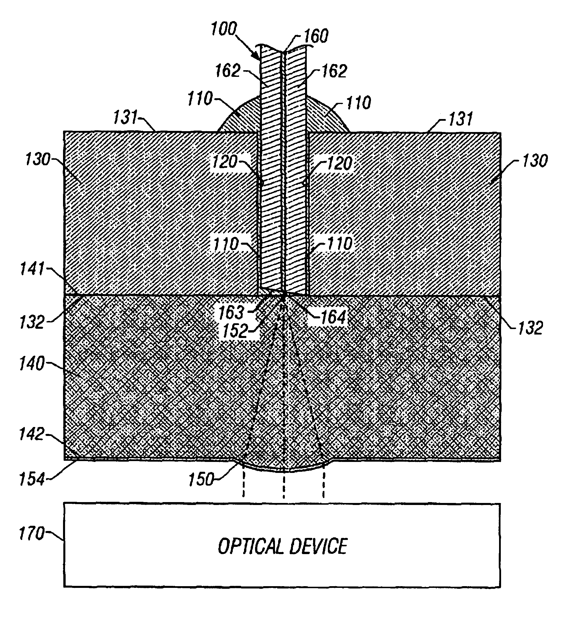
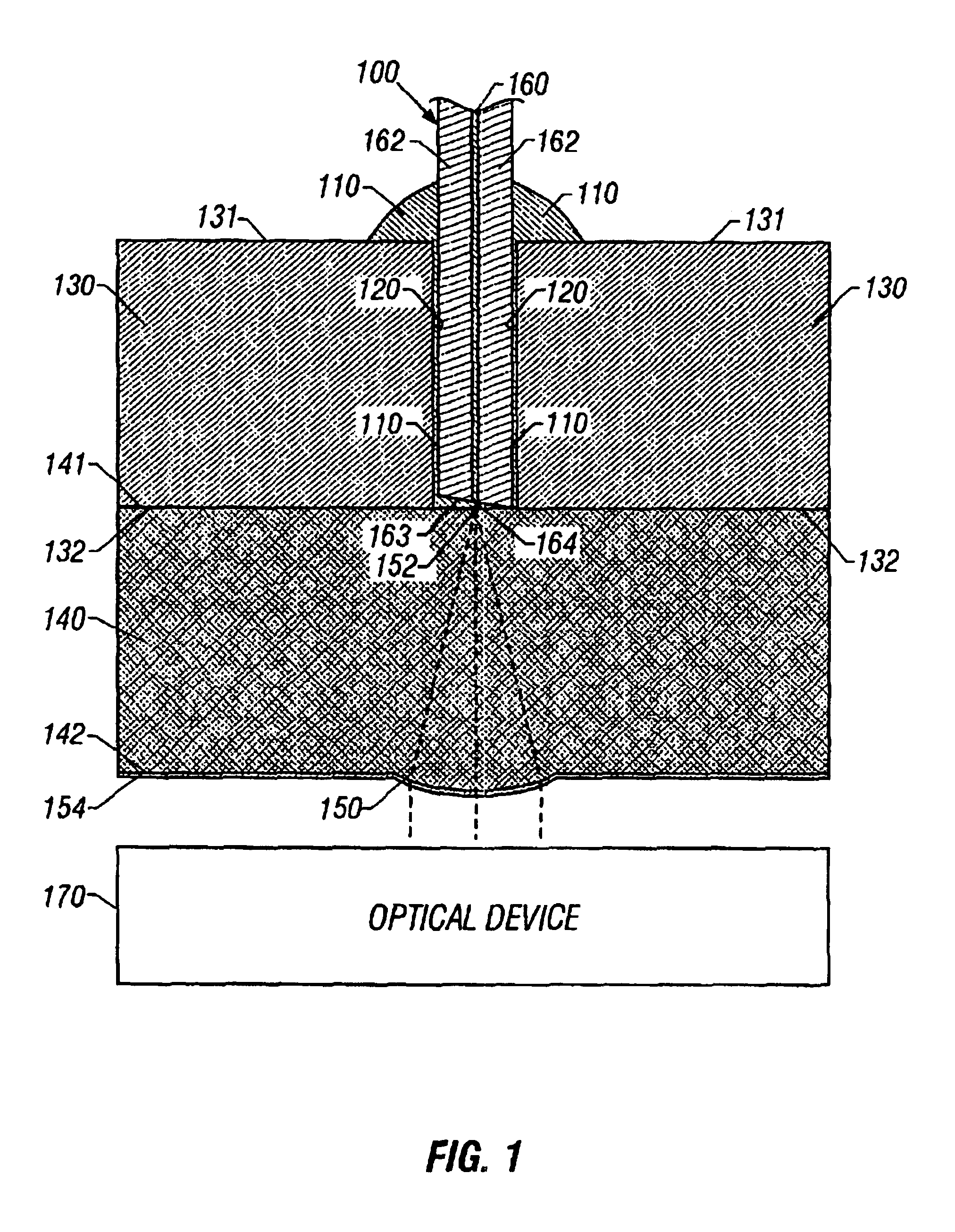
[0037]FIG. 1 is a cross-sectional view of an optical fiber coupler constructed in one embodiment of the invention. An optical fiber 100 is affixed by a suitable adhesive 110 such as an optical epoxy into a fiber socket 120, which is a through hole that has been deep-etched completely through a first layer 130. In this embodiment the first layer 130 comprises silicon that has a form suitable for etching, such as single-crystal silicon. The fiber socket 120 extends completely through the first layer from a top surface 131 to a lower surface 132. The lower surface 132 of the first la...


PUM


Abstract

A multilayer optical fiber coupler for coupling optical radiation between an optical device and an optical fiber, including a first layer that has a fiber socket formed by photolithographic masking and etching to extend through said first layer, and a second layer bonded to the first layer. The first layer may comprise substantially single-crystal silicon. An optical fiber is inserted into the fiber socket to align the optical fiber precisely within the fiber socket. In one embodiment the optical fiber is a single mode fiber, and an optical focusing element formed on the second layer is aligned with the core of the single mode fiber. The second layer may comprise glass having an index of refraction that approximately matches the index of the optical fiber, and an optical epoxy is used to affix the optical fiber into the fiber socket and fill the gaps between the end face of the fiber and the second layer. Embodiments are disclosed in which an optical device such as a VCSEL or photodetector is bonded to the second layer. Alternative embodiments are disclosed in which the optical device is incorporated into the second layer. Advantages include reduced cost due to batch fabrication techniques, and passive alignment of the optical fiber.

Description

CROSS REFERENCE TO RELATED APPLICATIONS[0001]Priority is hereby claimed to U.S. Provisional Application No. 60 / 088,374, filed Jun. 8, 1998 entitled LOW COST OPTICAL FIBER TRANSMITTER AND RECEIVER and U.S. Provisional Application No. 60 / 098,932, filed Sep. 3, 1998 entitled LOW COST OPTICAL FIBER COMPONENTS.BACKGROUND OF THE INVENTION[0002]1. Field of the Invention[0003]The present invention generally relates to couplers for coupling optical radiation into and out of an optical fiber.[0004]2. Description of Related Art[0005]Optical fibers have by far the greatest transmission bandwidth of any conventional transmission medium, and therefore optical fibers provide an excellent transmission medium. An optical fiber is a thin filament of drawn or extruded glass or plastic having a central core and a surrounding cladding of lower index material to promote internal reflection. Optical radiation (i.e. light) is coupled (i.e. launched) into the end face of an optical fiber by focusing the lig...

Claims


Application Information

Patent Timeline
IPC IPC(8): G02B6/36G02B6/00G02B6/42
CPCG02B6/4204G02B6/4206G02B6/4224G02B6/423G02B6/4239
Inventor JIAN, BENJAMIN
Owner JIAN BENJAMIN
Why Eureka
Try Eureka