

Composite hollow insulator core-rod and making method
A technology for insulators and mandrels, applied in the field of composite hollow insulator mandrels and its preparation, can solve the problems of large size and weight, simplicity, etc., achieve excellent electrical performance, take into account economy, and ensure the effect of mechanical performance requirements
- Summary
- Abstract
- Description
- Claims
- Application Information
AI Technical Summary
Problems solved by technology
Method used
Image

Examples
preparation example Construction
[0017] The preparation method of the present invention will be further described below in conjunction with specific examples and accompanying drawings, but the present invention is not limited.
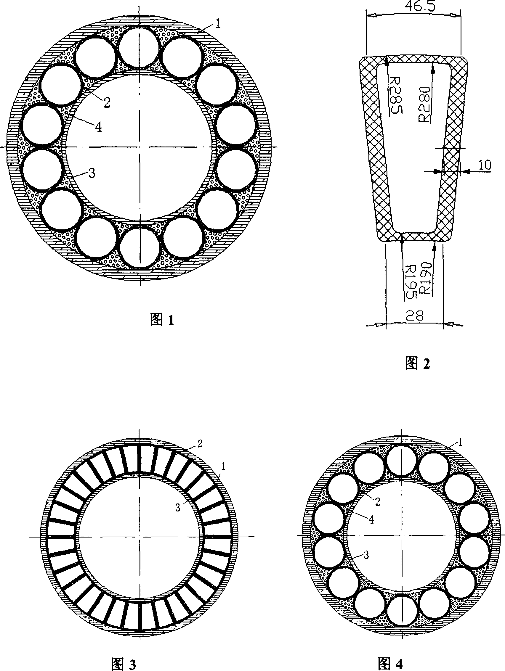
[0018] Firstly, according to the load level of the insulator, the size and shape of the mandrel are calculated and determined. The cross-section is shown in Figure 1. The production process is as follows: First, a certain number of composite material profiles 2 are produced for use, then the glass fiber reinforced resin matrix composite material tube 3 is wound or rolled, and then the composite material profiles 2 are installed. The gaps between the profiles are made of glass fiber and resin The composite material filler 4 composed of the mixture is filled, and finally the glass fiber reinforced resin matrix composite material pipe 1 is wound or cloth rolled. Among them, the composite material profile 2 has various forms, including fan-shaped, trapezoidal, circular, triangular, I-shap...
Embodiment 1
[0019] Example 1: The use requirements of 1000KV outdoor rod insulators are as follows: the length is 12m, the bending moment to the root is 200KN·m, and the torque is 10KN·m. The mandrel is made of glass fiber reinforced epoxy resin composite material, and the outer diameter is designed to be 600mm after calculation.
[0020] The intermediate profile (composite profile 2) adopts a hollow fan-shaped structure and is pultruded. The size is shown in Figure 2, a total of 32, each of which is bonded with epoxy resin. The longitudinal section of the entire mandrel is shown in Figure 3. After testing, the mandrel meets the mechanical and electrical performance requirements.
Embodiment 2
[0021] Example 2: The requirements for use of a 500KV outdoor rod insulator are as follows: the length is 8m, the bending moment to the root is 100KN·m, and the torque is 5KN·m. The mandrel is made of glass fiber reinforced epoxy resin composite material, and the outer diameter is designed to be 350mm after calculation, and the intermediate profile (composite material profile 2) is a round tube, a total of 14 pieces. The dimensions of each part are shown in Table 2.
[0022] The gaps between the intermediate profiles are filled with a composite filler 4 consisting of a glass fiber and epoxy resin mixture. The longitudinal section of the entire mandrel is shown in Figure 4. After testing, the mandrel meets the mechanical and electrical performance requirements.
[0023] schedule
[0024] Table 1 Tube 1, 3 size
[0025] Outer diameter / mm
Wall thickness / mm
Outer tube 1
inner tube 3
600
380
15
10
[0026] Table 2 Dimens...
PUM
| Property | Measurement | Unit |
|---|---|---|
| Wall thickness | aaaaa | aaaaa |
| Length | aaaaa | aaaaa |
| Outer diameter | aaaaa | aaaaa |
Abstract
Description
Claims
Application Information