Liquid-cooled radiating system

A cooling system, liquid cooling technology, applied in cooling/ventilation/heating transformation, electrical components, electrical solid devices, etc., can solve the problems of wasting energy, unable to achieve timely, high-efficiency heat exchange, burning computer chips, etc., to save energy The effect of electric energy, energy saving and component loss reduction

Inactive Publication Date: 2007-03-28
HONG FU JIN PRECISION IND (SHENZHEN) CO LTD +1
View PDF0 Cites 9 Cited by
  • Summary
  • Abstract
  • Description
  • Claims
  • Application Information

AI Technical Summary

Problems solved by technology

Therefore, when the heat generated by the computer chip is small, the energy used to drive the power pump will be wasted; when the heat generated by the computer chip is large, it will be impossible to achieve timely and efficient heat exchange, and even burn the computer chip

Method used


Image

  • Liquid-cooled radiating system

Examples


Embodiment Construction

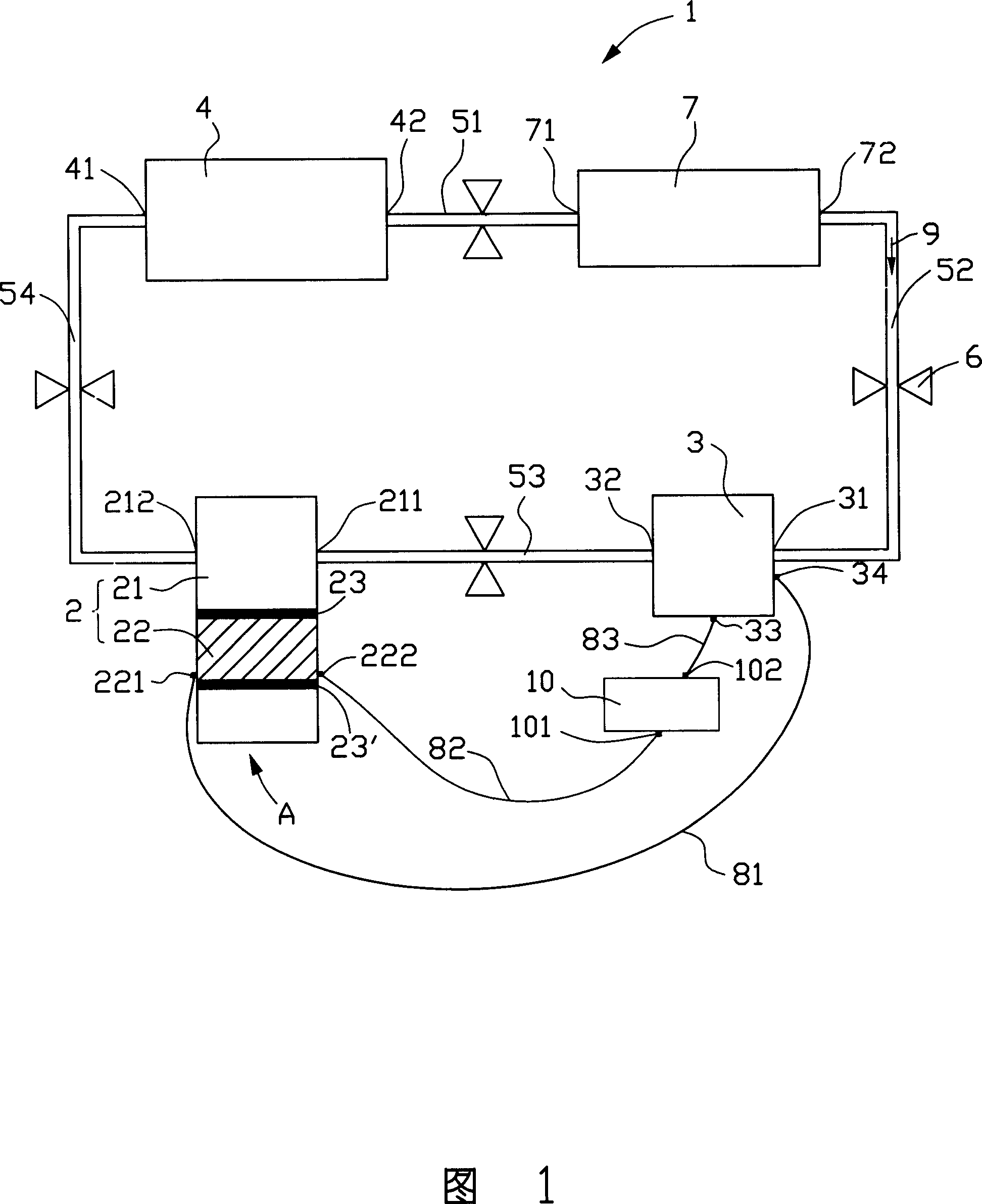
[0010] Generally, when there is a temperature difference between opposite end surfaces of a thermoelectric material, an electromotive force E is generated between the two end surfaces. This is the Siberk effect. The electromotive force generated due to the Siberk effect is called thermoelectric electromotive force. If the thermoelectric material is made into a thermoelectric converter and placed in a loop, when there is a temperature difference between the opposite ends of the thermoelectric converter, a current will be generated at the electrical output of the thermoelectric converter, and the current will flow along the loop. back to the electrical input of the thermoelectric converter, thereby forming an electrical loop.

[0011] Below, the present invention will be further described in detail in conjunction with the accompanying drawings.

[0012] Referring to Fig. 1, a liquid-cooled heat dissipation system 1 of a preferred embodiment of the present invention includes: a...


PUM


Abstract

The liquid cooling typed cooling system includes following parts: heat elimination element with heat elimination division; working fluid circulated inside the cooling system; a condensation division for condensing the working fluid from the heat elimination division; a pump for making circulation of the working fluid; the heat elimination element also includes a thermoelectric conversion division close fitted to the heat elimination division. Being connected to the pump electrically, the thermoelectric conversion division is in use for providing power for the pump. The liquid cooling typed cooling system carries off heat in high efficiency and in time as well as saves energy.

Description

【Technical field】 [0001] The invention relates to a heat dissipation system, in particular to a liquid-cooled heat dissipation system. 【Background technique】 [0002] With the advancement of science and technology, the processing speed of various electronic devices, such as computers, printers, copiers, etc., has become increasingly high-speed, resulting in a corresponding increase in the heat generated inside the above-mentioned electronic devices. The current heat dissipation method is generally in electronic components such as chips A heat dissipation fan is installed on the top to assist heat dissipation by air cooling, but the heat dissipation efficiency of the heat dissipation fan is limited, and the effect on reducing the temperature of the chip is poor, and there will be noise when the fan is running. [0003] In order to solve the problem of low heat dissipation efficiency and noise of the cooling fan, a liquid-cooled heat dissipation device has begun to appear, whi...

Claims


Application Information

Patent Timeline
Patent Type & Authority Applications(China)
IPC IPC(8): H01L23/473H05K7/20
CPCH01L2924/0002
Inventor 简士哲
Owner HONG FU JIN PRECISION IND (SHENZHEN) CO LTD
Why Eureka
Try Eureka