
Stepless speed regulating well repairing device

A technology for stepless speed regulation and workover, which is applied in drilling equipment, drilling equipment and methods, and earth-moving drilling, etc., can solve the problems of complex structure of workover rig, large braking torque, frequent clutch clutch, etc. The effect of reducing equipment maintenance, small braking torque and reducing operating time

Active Publication Date: 2007-04-11
山东创新石油技术有限公司
View PDF0 Cites 0 Cited by
  • Summary
  • Abstract
  • Description
  • Claims
  • Application Information

AI Technical Summary

Problems solved by technology

This kind of power source must convert fuel into power through the engine, and then the output shaft drives the gearbox to drive the winch drum, and its efficiency is relatively low
After the oil pipe or oil rod is raised or lowered, in order to ensure the next work and the work of the hydraulic tongs, the engine cannot stop running, and the stop of the winch drum must be separated from the engine power, so that a clutch must be used between the engine and the winch drum to work When the clutch is frequently disengaged, the operation is cumbersome and the structure is complicated
Due to the structure of the workover rig using the engine as the power source, the brake can only brake the winch drum, resulting in large braking torque, fast wear and high maintenance costs.
Based on the above reasons, the fuel-powered engine-driven workover rig has the disadvantages of complex structure, bulky size, high cost, high operating cost and high maintenance cost.

Method used


Image

  • Stepless speed regulating well repairing device
  • Stepless speed regulating well repairing device
  • Stepless speed regulating well repairing device

Examples


Embodiment Construction

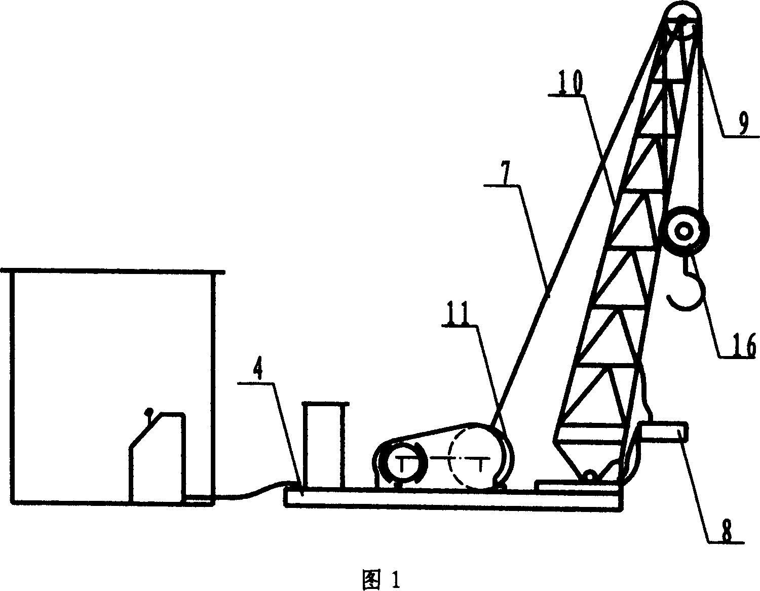
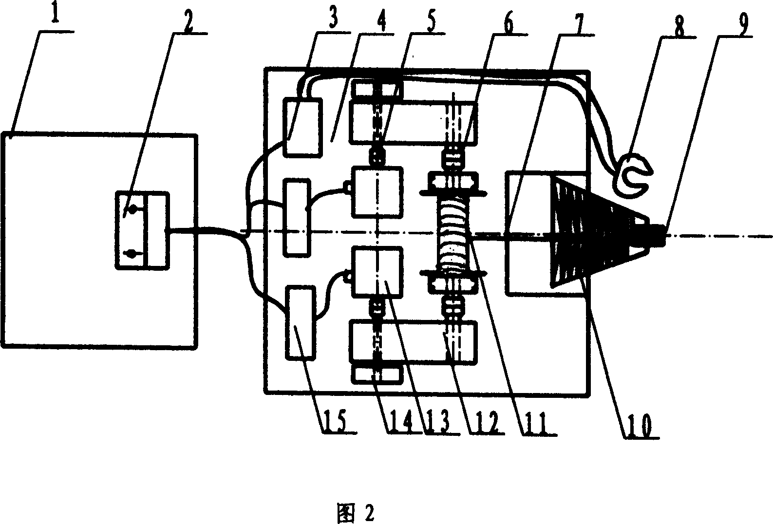
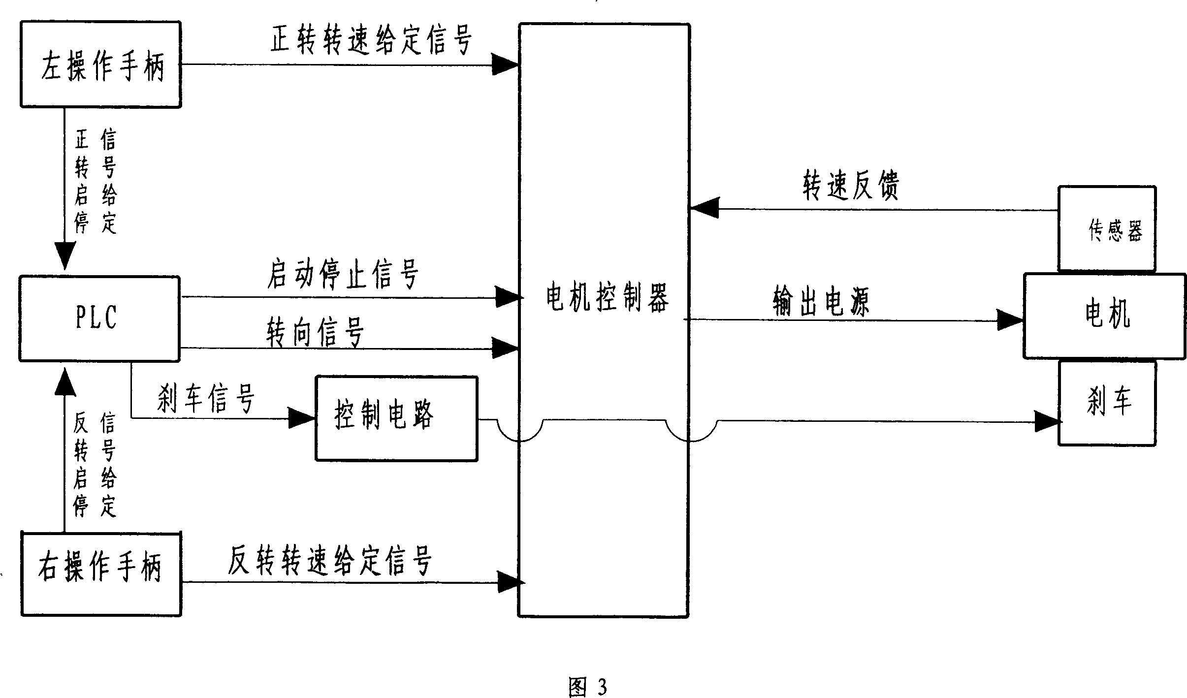
[0019] A stepless speed regulation workover device, as shown in Figure 2, consists of an operating room 1, a console 2, a hydraulic mechanism 3, a base 4, a motor coupling 5, a drum coupling 6, a wire rope 7, and a hydraulic clamp 8 , crown block 9, frame 10, drum 11, transmission 12, motor 13, brake brake 14, control cabinet 15, traveling block and hook 16, is characterized in that the base 4 is set as a rectangle, and the middle part of the base is horizontally arranged The drum 11, the motor 13 and the transmissions 12 on both sides; the frame 10 is fixed in the front middle of the base, the hydraulic mechanism 3 and the control cabinet 15 are installed in the rear of the base; the operating room 1 and the indoor console 2 are arranged in the middle of the rear of the base; The two ends of the drum are connected with the output shaft of the transmission 12 with the drum coupling 6, the motor shaft is connected with the input shaft of the transmission with the motor coupling ...


PUM


Abstract

The stepless speed regulating well repairing apparatus consists of operating room, console, hydraulic mechanism, pedestal, hydraulic tongs, crown block, frame, roller, speed variator, motor, brake, control cabinet, traveling pulley and rotary hook connected together. The present invention has the advantages of simple operation and low power consumption.

Description

1. Technical field [0001] The invention belongs to general workover equipment for oilfields, in particular to a stepless speed regulation workover device. 2. Background technology [0002] At present, during workover in oilfields, diesel, gasoline, and gas engines are usually used as the power source of workover machines to achieve the purpose of lifting or lowering oil well strings and downhole tools. This power source must convert fuel into power through the engine, and then the output shaft drives the gearbox to drive the winch drum, and its efficiency is relatively low. After the oil pipe or oil rod is raised or lowered, in order to ensure the next work and the work of the hydraulic tongs, the engine cannot stop running, and the stop of the winch drum must be separated from the engine power, so that a clutch must be used between the engine and the winch drum to work When the clutch is frequently disengaged, the operation is cumbersome and the structure is complicated. ...

Claims


Application Information

Patent Timeline
Patent Type & Authority Applications(China)
IPC IPC(8): E21B19/00E21B7/00
Inventor 刘超刘明华牟少平李鹏宋玉全
Owner 山东创新石油技术有限公司
Learn More