

Super conducting energy saving desalination drinking water making system of ocean ship
A drinking water system and superconducting technology, applied in seawater treatment, heating water/sewage treatment, light water/sewage treatment, etc., can solve problems such as inconvenience to crew members and passengers, waste of limited energy for sailing, and occupation of valuable space on the ship, etc., to achieve Reduced load, simple structure, and improved utilization
- Summary
- Abstract
- Description
- Claims
- Application Information
AI Technical Summary
Problems solved by technology
Method used
Image

Examples
Embodiment 1
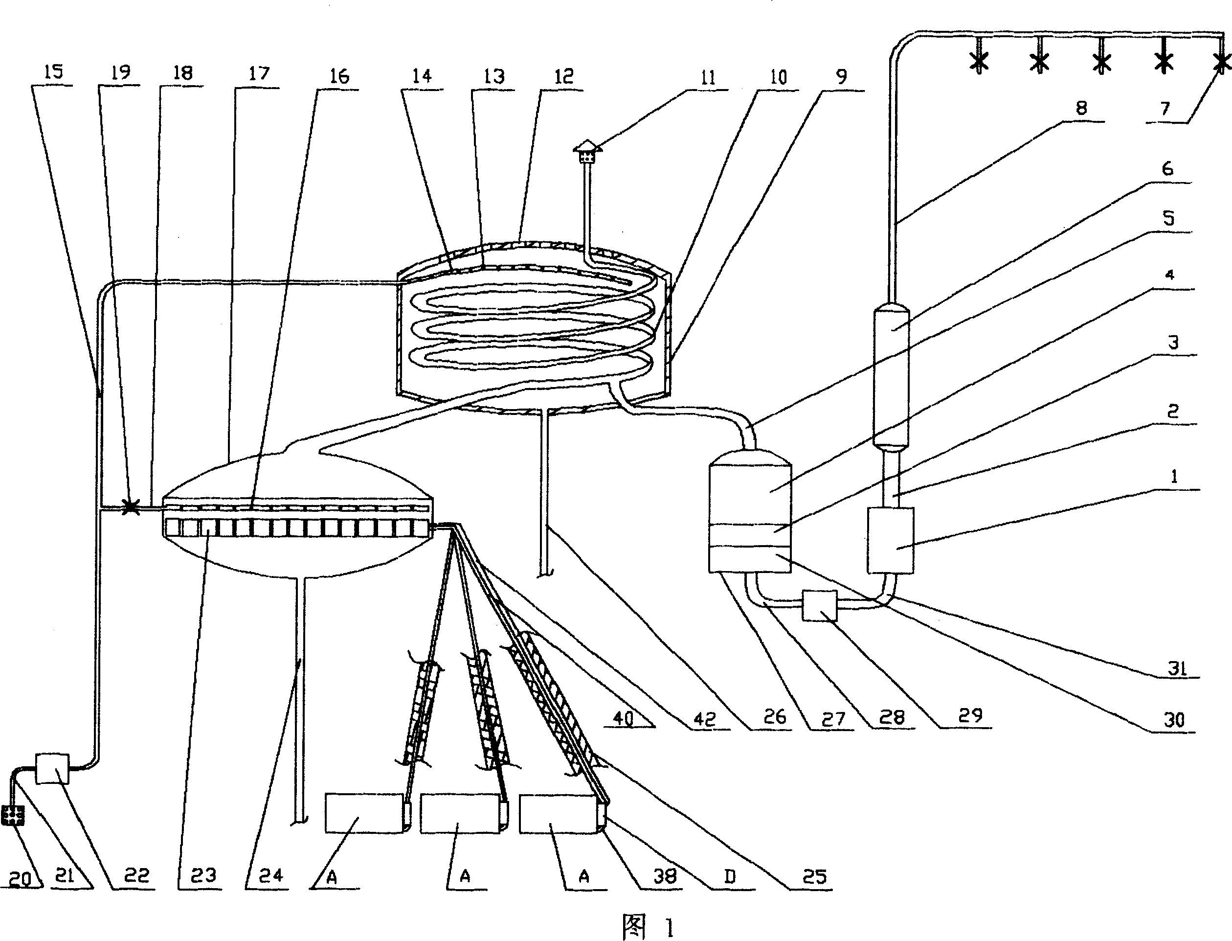
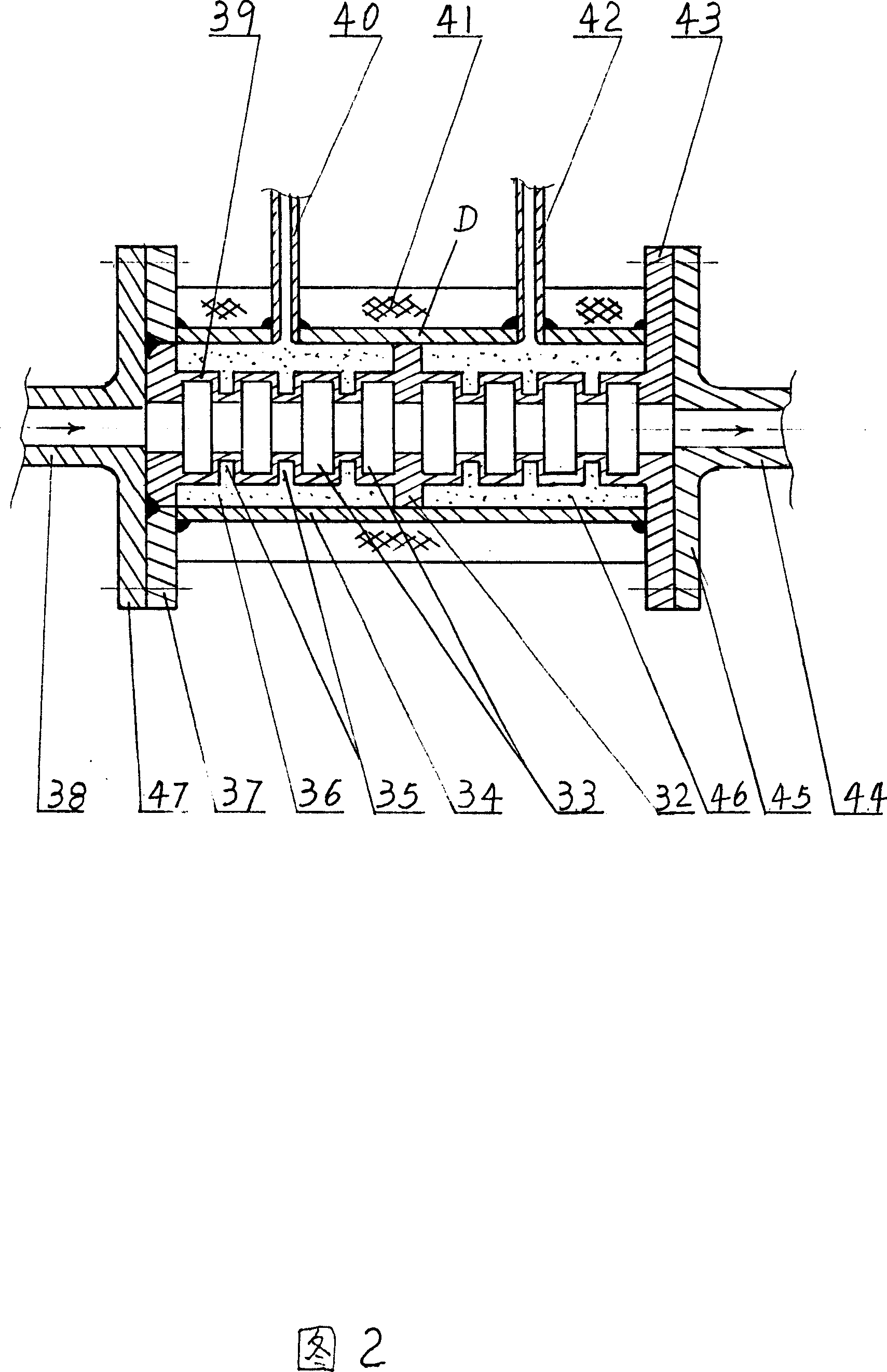
[0016] Embodiment 1: As shown in Figure 1 and Figure 2, a superconducting heat collecting tube D is installed on the exhaust port of the internal combustion unit A. The superconducting heat pipes 40, 42 on the heat cylinder D are connected on the heat dissipation plate 23 in the reaction tank 17, the top of the heat dissipation plate 23 is equipped with a spray pipe 18, and the top of the reaction tank is connected with the disc cooling tube 10, and the disc cooling tube 10 is contained in the cooling tank 9. The top of the cooling tank 9 has cooling holes 12 to communicate the cooling tank with the outside atmosphere, and the top of the cooling tank 9 is equipped with a shower pipe 14 . The top of the disc-shaped cooling pipe 10 is an exhaust port 11, and the bottom of the disc-shaped cooling pipe 10 is equipped with a water receiving pipe 5, which communicates with the disc-shaped cooling pipe 10, and the water receiving pipe 5 is connected to the water storage tank 27. The...
Embodiment 2
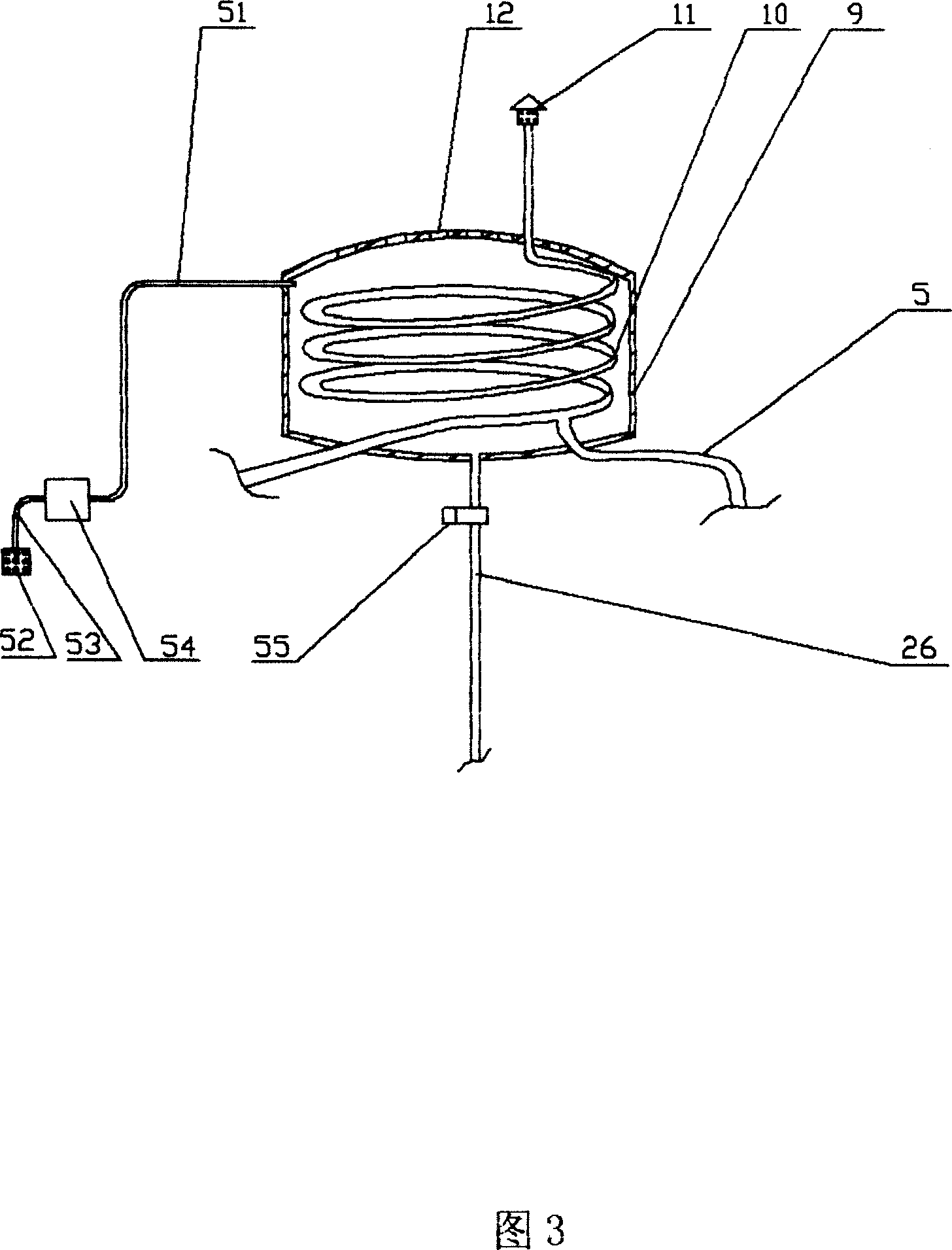
[0020] Embodiment 2, this embodiment is basically the same as Embodiment 1, as shown in Figure 3, just does not install spray pipe in cooling tank 9, but has water pump 51 to extract seawater through water inlet pipe 51 and directly sends into cooling tank 9 , the cooling tank 9 is filled with seawater, and the disc-shaped cooling pipe 10 is directly cooled by seawater. On the drain pipe 26 below the cooling tank 9, an electric regulating valve 55 is additionally installed to control the amount of draining water, so that the cooling tank 9 is always filled with seawater for improving the cooling effect. Of course, the cooling tank 9 can also be omitted, and the disc-shaped cooling pipe 10 is placed in the air to allow the sea breeze to cool it naturally, which is slightly insufficient in the amount of water produced in tropical regions.
[0021] The invention utilizes the high-temperature waste heat generated when the ship's internal combustion engine is ignited and blasted to...
PUM
 Abstract
Description
Claims
Application Information