Active shock absorption system for magnetorheological elastomer and control method therefor

A magneto-rheological elastomer and active technology, applied in the direction of vibration suppression adjustment, non-rotational vibration suppression, springs, etc., can solve the problems of non-adjustable vibration damping frequency, non-adjustable frequency, narrow vibration damping frequency band, etc., to reduce motion damping , high energy utilization rate, and the effect of vibration reduction frequency bandwidth

Inactive Publication Date: 2007-04-25
UNIV OF SCI & TECH OF CHINA
View PDF1 Cites 27 Cited by
  • Summary
  • Abstract
  • Description
  • Claims
  • Application Information

AI Technical Summary

Problems solved by technology

However, due to its non-adjustable frequency, it can use less energy to achieve a better vibration reduction effect compared with passive vibration absorbers near the natural frequency of the vibration absorber, but when the vibration frequency slightly deviates from the natural frequency of the vibration absorber, the same vibration reduction The energy required for the vibration effect increases sharply, so the frequency band that can be practically applied is still only around the natural frequency of the vibration absorber, so the vibration reduction frequency band is narrow
[0004] CN01272733.4 patent discloses a non-frequency-adjustable active vibration absorber, which uses a spring vibrator for energy storage, which has low energy consumption and obvious vibration damping effect, but because its vibration damping frequency is still not adjustable, it is different from the previous mentioned Like the non-frequency adjustable shock absorber, the vibration reduction frequency band is still narrow

Method used


Image

  • Active shock absorption system for magnetorheological elastomer and control method therefor
  • Active shock absorption system for magnetorheological elastomer and control method therefor

Examples


Embodiment Construction

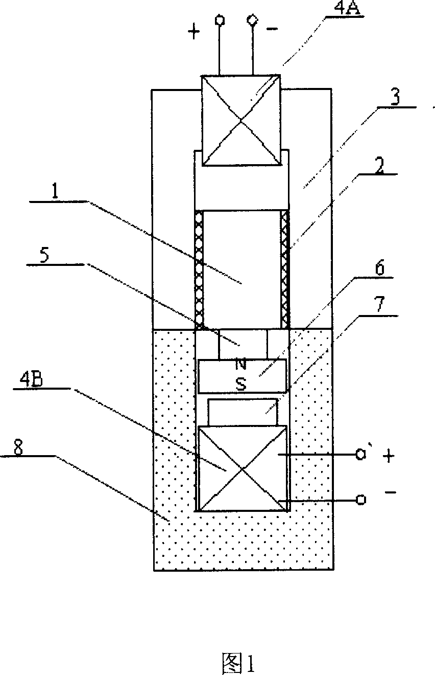
[0024] See Fig. 1, 1 is the vibration absorbing block, the sheet-like magnetorheological elastomer 2 is arranged on the left and right sides of the vibration absorbing block, and bonded into one, the opening of the "U"-shaped electromagnet 3 is downward, and it is connected to the external power supply The coil 4A is wound on the top thereof, and the other surface of the sheet-shaped magnetorheological elastomer 2 is bonded to the inner surface of the "U"-shaped iron core respectively. A magnetic isolation block 5 of brass material is fixedly connected to the lower end surface of the vibration absorbing block by means of screw connection, and the permanent magnet 6 is fixedly connected to the lower end surface of the magnetic isolation block 5 . 7, the electromagnet of square, it is fixed on the inner bottom surface of " U " shape support 8, and its coil 4B is connected with external power supply.

[0025] The lower ends of the two side walls of the "U"-shaped iron core form a...


PUM


Abstract

The invention relates to a damping device, especially active vibration absorber and the control method. Said vibration absorber in vibration absorbing system comprises main drive part, vibration absorbing block, changeably stiffness part, magnetic insulation block and U-shaped bracket. The main drive part comprises permanent magnet and column electromagnet. The column iron core is fixed on the bottom of bracket and permanent magnet is fixed with vibration absorbing block by magnetic insulation block. The changeably stiffness part comprises U-shaped electromagnet and MR elastomer. U-shaped iron core is opened downward, of which MR elastomer are set on two inner sides respectively. Vibration absorbing block is set among two chips and the lower end of U-shaped iron core is fixed with the upper end of U-shaped bracket to form inner space where the main drive part, vibration absorbing block, MR elastomer and magnetic insulation block are accommodated. The control method is that the changeably stiffness part and main drive part are controlled respectively according to frequency, amplitude value and phase information of vibration-damping objects. The invention belongs to half-active and active combined control and is provided with low consuming and wide vibration-damping frequency so on.

Description

technical field [0001] The invention relates to a vibration damping device and a control method applied to mechanical equipment, in particular to an active vibration absorber and a control method. Background technique [0002] The vibration absorption system is very important to various mechanical equipment and electrical equipment. According to different power sources, the vibration absorption system can be divided into two types: passive type and active type. The traditional vibration absorber is usually passive. It does not need to consume external energy, has a simple structure, and can have a good vibration reduction effect on fixed excitation frequency vibrations. Therefore, it is widely used in many mechanical rotating parts caused by eccentric mass The damping aspect of the forced vibration. But this kind of passive vibration absorber has two major defects. First, it is not suitable for occasions where the frequency changes greatly. Second, the tuning speed is slow...

Claims


Application Information

Patent Timeline
Patent Type & Authority Applications(China)
IPC IPC(8): F16F9/53
CPCF16F1/361
Inventor 孙红灵龚兴龙张鲲张培强张先舟
Owner UNIV OF SCI & TECH OF CHINA
Why Eureka
Try Eureka