Underground gas storage well shaft and its fixing method

A gas storage well and wellbore technology, which is applied to the wellbore of gas underground gas storage well and its fixing field, can solve the problems of difficult construction, poor safety, inconvenient maintenance, etc. Effect

Inactive Publication Date: 2007-04-25
自贡力源科技有限公司
View PDF1 Cites 15 Cited by
  • Summary
  • Abstract
  • Description
  • Claims
  • Application Information

AI Technical Summary

Problems solved by technology

Although this method overcomes the problem of the shallow filling depth of cement slurry in the traditional method and the inability to discharge air and groundwater, which affects the fixation of the bottom and bottom of the wellbore; The well shaft is rigid, and the grouting hose is easily crushed so that the cement slurry cannot be poured down. At the same time, the cement slurry poured under the well is very easy to hold up the cylinder, making the construction difficult, and it is difficult to pour the cement slurry from the bottom to the ground. , which affects the fixed effect
In addition, the wellbore is a cylindrical metal tube, the bottom of the cylinder is a spherical sealing head, and there is no structure to prevent the rotation of the cylinder, the adhesion force of the cement slurry to it is poor, and it is difficult to solidify the wellbore and the well wall into one
Therefore, regardless of the above-mentioned cementing method used for the gas storage wellbore of this structure, the manufacturability and reliability of cement slurry injection are poor. Especially when the ambient temperature changes greatly, the wellbore will suddenly rush out for a long section in severe cases (multiple accidents have occurred), which not only affects normal use, but also poses a threat to the safety of facilities and staff
Therefore, the above-mentioned background technology has the structure of the wellbore, especially the unreasonable design of the bottom structure of the wellbore, the manufacturability and reliability of the corresponding installation and fixing methods, and the inability to inject cement slurry to the bottom of the wellbore and between the wellbore and the well wall through the inner cavity of the wellbore. It is difficult to fasten the wellbore and the well wall into one body through cement slurry; poor safety in use, inconvenient maintenance and service life and other disadvantages

Method used


Image

  • Underground gas storage well shaft and its fixing method
  • Underground gas storage well shaft and its fixing method

Examples


Embodiment Construction

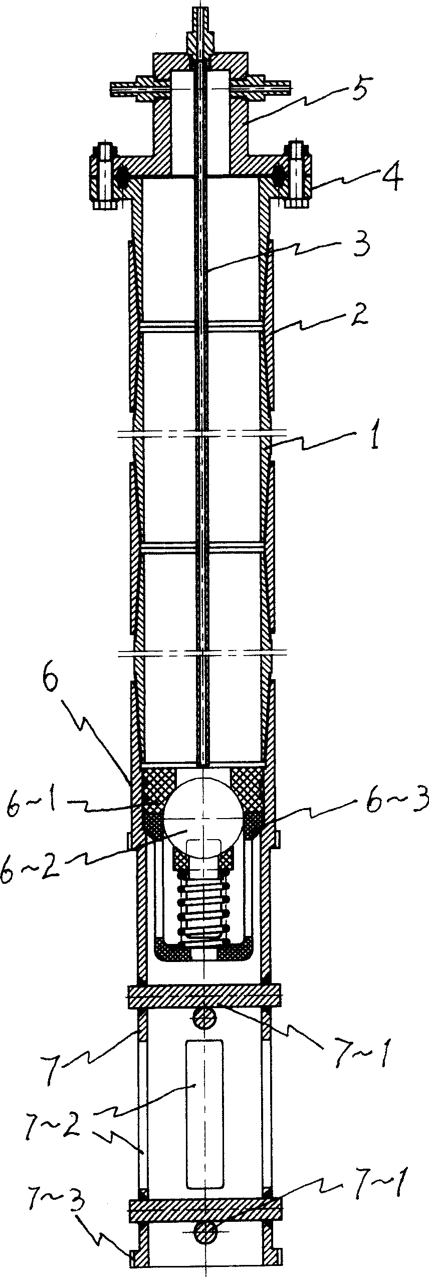
[0015] Taking the wellbore with an outer diameter of 7 (177.8mm) and a total effective gas storage length of 120m as an example:

[0016] The cylinder body 1, the connecting sleeve 2, the drain pipe 3, the wellhead flange 4, and the four-way control head 4 are all the same as the background technology. The valve body 6 in this embodiment adopts a 7-hour conduit back pressure valve for drilling in oil and gas fields; the fixed frame 7 adopts the same 7-hour conduit as the cylinder 1 and is welded to the lower mouth of the valve body 6, the axis height is 1200mm and passes through two sets of ribs Diameter is the cross bar 7-1 of φ 30mm to strengthen, and 4 frame holes 7-2 of 800 * 50mm (high * wide) are opened symmetrically on the tube wall, and bottom ring 7-3 is a toothed bottom ring, external diameter φ 20mm.

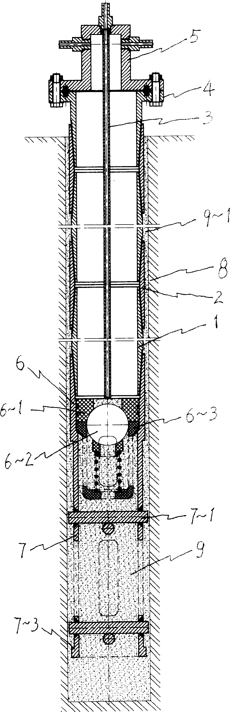
[0017] The fixing method is as follows: first, according to the oil and natural gas drilling procedures and requirements, drill a foundation well with a diameter of φ...


PUM


Abstract

The invention relates to a mine shaft of high-pressure gas underground storage well and the fixed method. The mine shaft comprises shaft body, connecting sleeve, four-way control head, one-way sealing head and foundation fixed bracket on the bottom, and drainage pipe. The fixed method comprises drilling base well, setting shaft body, producing cement slurry, cement slurry perfusion along inner cavity of mine shaft and one-way valve, installing drainage pipe and four-way control head. Because of one-way valve applied as bottom sealing head of mine shaft, base fixed bracket added, and cement slurry perfusion improved, it is provided with reasonable structure design, convenient and stable operation for perfusion, fixed connection between the mine shaft and well wall, good safety, convenient repair and maintenance, and longer service life so on. Inconvenient assembling and fixing well shaft, small attachment force with cement, bad stability of perfusion fixing technology, uneasy operation, mine shaft rotating or moving in working and bad safety are conquered.

Description

technical field [0001] The invention belongs to the shaft of an underground gas storage well and a fixing method thereof, in particular to a shaft for matching with a high-pressure underground gas storage well of natural gas and a method for installing and fixing the shaft in a foundation well. Background technique [0002] In the patent document with the notification number CN2281418y and the name "High Pressure Gas Underground Gas Storage Well", the disclosed casing thread is used to connect the joints of the cylinders to form a well body, and the wellhead method is set at the upper mouth. A spherical head is set at the bottom of the wellbore to form the main body of the wellbore; a four-way control head is set on the wellhead flange, and a liquid discharge pipe from the four-way control head to the bottom of the wellbore is arranged in the cylinder body to form an underground gas storage well. Wellbore for gas storage. After the wellbore is lowered into the foundation we...

Claims


Application Information

Patent Timeline
Patent Type & Authority Applications(China)
IPC IPC(8): F17C1/00F17C13/00F17C13/04F17C13/08
Inventor 冉训
Owner 自贡力源科技有限公司
Why Eureka
Try Eureka