Laser welding system

A technology of laser welding and laser emission system, applied in the field of systems using laser welding workpieces, can solve the problems of uneven welding, heat can not be removed in time, affecting the appearance of products, etc., to avoid uneven heating and smooth welding surface. Effect

Inactive Publication Date: 2007-05-02
HONG FU JIN PRECISION IND (SHENZHEN) CO LTD +1
View PDF0 Cites 5 Cited by
  • Summary
  • Abstract
  • Description
  • Claims
  • Application Information

AI Technical Summary

Problems solved by technology

Although the existing laser welding technology is fast, there is still some heat in the welding part of the workpiece that cannot be removed in time, which will cause some unevenness in the welding part, which will affect the appearance of the product

Method used


Image

  • Laser welding system
  • Laser welding system

Examples


Embodiment Construction

[0012] The laser welding system will be further described in detail with reference to the accompanying drawings and embodiments.

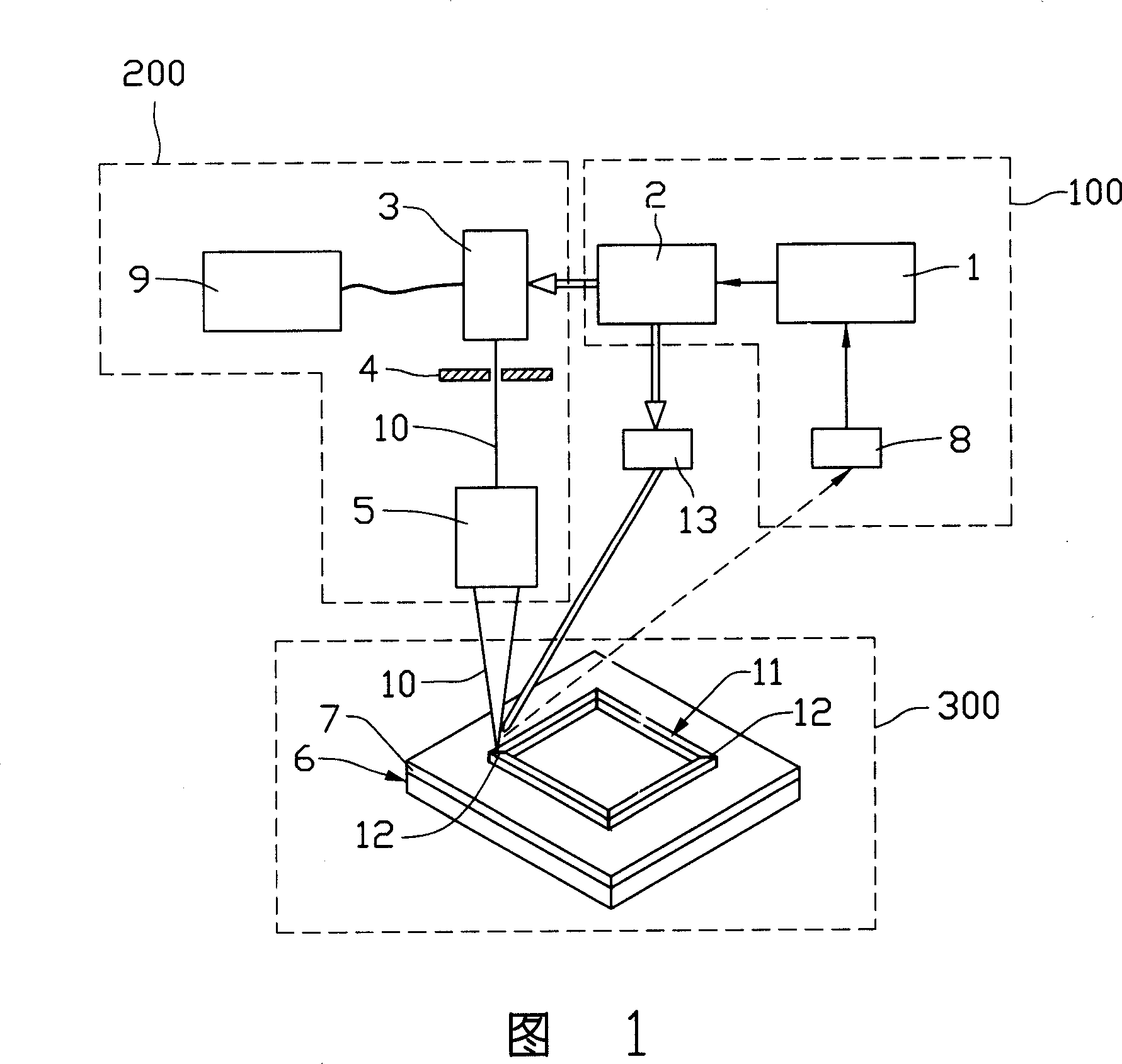
[0013] Please see FIG. 1 , which is a schematic diagram of a laser welding system according to an embodiment of the present invention, which includes: a control system 100 , a laser emitting system 200 and a receiving system 300 . The control system 100 is connected with the laser emitting system 200 to control (the double straight arrow in the figure represents control) the laser emitting system 200 emits the laser light 10 and irradiates the receiving system 300, and the control system 100 is used for detection (dashed straight arrow means detection), process the information from the receiving system 300, and further adjust and control the laser emitting system 200 to emit the laser light 10 according to the information, forming a closed-circuit system, wherein the receiving system 300 includes a support frame 6 supporting the welding workpiece 11...


PUM

PropertyMeasurementUnit
diameteraaaaaaaaaa

Abstract

A laser welding system for the electronic products is composed of a laser emitting system, a laser receiving system with a supporting frame and at least one cooler on the surface of said supporting frame for dissipating the heat generated by laser welding, and a control system for controlling the laser emitting system for emitting laser beam onto the receiving system, and detecting and processing the information of receiving system to regulate and control laser emitting system, so forming a closed loop system.

Description

【Technical field】 [0001] The invention relates to metal welding technology in the fields of computer, communication, consumer electronics and the like, and in particular relates to a system for welding workpieces using laser light. 【Background technique】 [0002] Welding is a metal connection method for joining materials or workpieces by means of heat and pressure. Traditional welding methods include resistance welding, seam welding, and carbon dioxide welding. [0003] Resistance welding uses an electric current applied to the spot welding electrode to melt the contacting surfaces of the parts and then join them together under pressure. Seam welding is a spot welding electrode that uses a roller electrode instead of a resistance welding electrode. The roller electrode transmits welding current and pressure, and its rotation coordinates with the movement of the parts to produce a continuous weld. It is mainly used for sealing welding or seam spot welding workpieces. Carbon...

Claims


Application Information

Patent Timeline
Patent Type & Authority Applications(China)
IPC IPC(8): B23K26/20B23K26/42B23K26/06B23K26/12H01S3/00
CPCB23K26/423B23K26/0648B23K26/032B23K26/034B23K26/703
Inventor 陈杰良
Owner HONG FU JIN PRECISION IND (SHENZHEN) CO LTD
Why Eureka
Try Eureka