
Porous stay tube, preparation method and application

A technology of porous support and manufacturing method, applied in the direction of slender elements, building elements, etc., can solve the problems that the support position needs to be changed, the support structure cannot be applied well, the support structure cannot be used, and it is unfavorable for popularization and use, and the product quality is stable. The effect of good performance, improved support strength and strong rigidity

Inactive Publication Date: 2007-05-09
李明辉
View PDF2 Cites 1 Cited by
  • Summary
  • Abstract
  • Description
  • Claims
  • Application Information

AI Technical Summary

Problems solved by technology

Although the pipe or sheet can be provided with openings for support, it is not very suitable for the situation where the support position needs to be changed. In order to cooperate with the use of this situation, it is necessary to continuously and regularly arrange openings on the pipe or sheet When in use, the openings at different positions can be used to form a support structure. For example, the sheet material is a kind of "changeable shelf" disclosed by the Chinese utility model patent No. 200420047624. The small holes connected to the small shelves enable it to change the position of the small shelves connected to it according to different display requirements, so as to achieve various display purposes; but for the pipes, regular openings are continuously arranged to form a changing position. The supporting structure has not been reported
The Chinese utility model patent No. 03216901.9 discloses "a kind of sleeve-in steel pipe". The improved formation of steel pipe columns is mainly to use drilling or punching to open screw holes or elongated welding holes on the current steel pipe profiles, and these screw holes or elongated welding holes are not distributed on the wall of the entire steel pipe profile, but It is only opened at the position where a fixed connection is required, so this steel pipe cannot be used to form a support structure that can change positions
During the actual research and development process of the applicant, it was found that although the process of directly using punching or drilling on ready-made tubular profiles (such as the above-mentioned building material steel pipe column) can achieve the purpose of uniformly opening holes on the pipe, the operation is relatively difficult. During the processing, it is easy to cause the concave deformation of the pipe, and the processing speed is slow, the production efficiency is low, and the manufacturing cost is high. Therefore, this technology cannot be used for large-scale production and manufacturing of products, and it is not conducive to widespread use

Method used


Image

  • Porous stay tube, preparation method and application
  • Porous stay tube, preparation method and application
  • Porous stay tube, preparation method and application

Examples


Embodiment 1

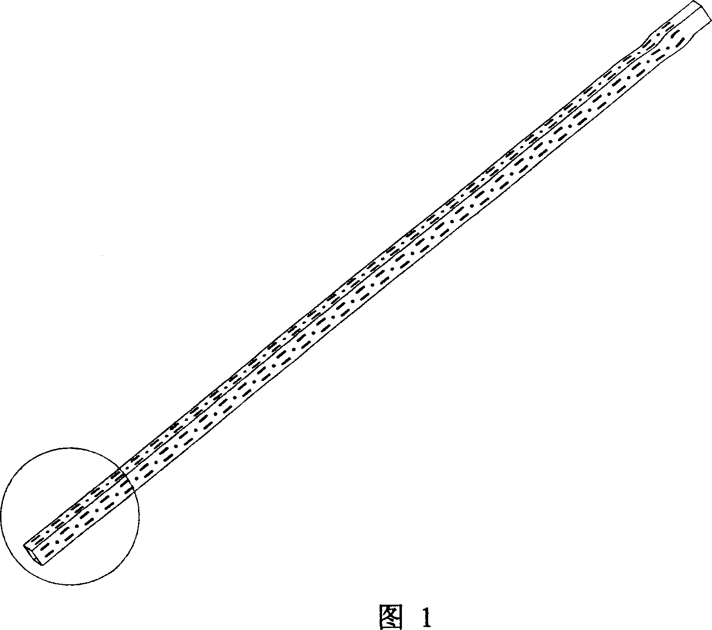
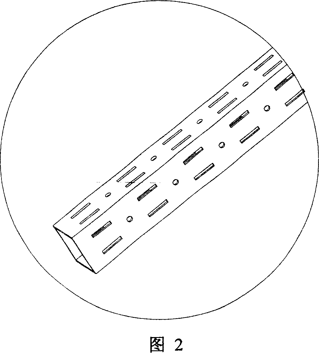
[0035] Fig. 1 and Fig. 2 have shown the specific structure of the present invention, as seen from Fig. 1, this porous support pipe comprises hollow pipe body, and the cross section of pipe body is square, and the four wall surfaces of described pipe body are integrally uniformly provided with for supporting Fixed through holes, the shape of the through holes is rectangular and circular, as shown in Figure 2; the through holes on each wall of the pipe body are arranged in the middle of the wall in the form of two parallel rows, and the position of the through holes on the opposite wall of the pipe body Symmetrical setting.

[0036] The method for manufacturing above-mentioned porous support pipe comprises the following steps:

[0037] (1) Continuous punching on the strip: cut the strip according to the size of the total section of the pipe body, and then put the cut strip into the punching machine for punching.

[0038] (2) Bending the punched strip, and butt joint shaping to ...

Embodiment 2

[0043] The structure of this porous support pipe is with the embodiment 1 shown in Fig. 1 and Fig. 2; Its manufacture method comprises the following steps:

[0044] (1) Continuous punching on the strip: Put a whole piece of plate into the punching machine for punching, and then cut the strip required for manufacturing a single pipe according to the size of the total section of the pipe body.

[0045] (2) The punched strip is rolled and formed by a rolling machine to form a pipe profile with a butt joint.

[0046](3) The butt joints of the pipe profiles are welded to form hollow porous support pipes. The specific welding process is to clamp and fix the pipe profile and place it in water or other cooling liquid, leaving only the butt joint on the water surface or the cooling liquid surface; at the same time, a cooling nozzle is installed behind the welding torch. Move, spray water or coolant to cool the solder joints immediately to prevent the pipe profile from twisting or shri...

Embodiment 3

[0050] The structure and manufacturing method of the porous support tube of this embodiment are the same as those in Example 1. The structure of its application is shown in Figure 5. The porous support tube can be used to form a telescopic support structure. As can be seen from Figure 5, the porous support tube includes two section sections. For the porous support tubes 1-1 and 1-2 of different sizes, the section 1-1 with a smaller section is inserted into the section 1-2 with a larger section, but the size and position of the holes set in the two sections of porous support tubes Correspondingly, the clamping block 7 can be used to snap into the corresponding holes of the two sections of porous support tubes 1-1, 1-2 that are socketed together, and the relative positions of the two sections of porous support tubes 1-1, 1-2 can be checked. fixed. When the block 7 is pulled out, the relative position between the two sections of porous support tubes 1-1, 1-2 can be adjusted relat...


PUM


Abstract

A method for preparing support tube with multihole includes punching continuous holes on strip material, folding strip material with punched holes, reshaping and butt-jointing folded material to form tubular product with butt-joint edge, welding butt-joint edge of tubular product for obtaining hollow support tube with multihole.

Description

technical field [0001] The invention relates to support pipe technology, in particular to a porous support pipe and its manufacturing method and application. Background technique [0002] The existing supporting materials mainly include pipes and sheets, usually with a relatively simple structure. The cross-section of the pipe is generally circular, and the pipe wall is a complete wall. Holes can be opened or support connectors can be installed at the positions that need support. , used to connect the support plate or support frame to form a support structure; the sheet is generally elongated, with connection holes provided on the sheet, and the support plate or support frame is provided with a connecting block extending into the connection hole to form a support structure . Although the pipe or sheet can be provided with openings for support, it is not very suitable for the situation where the support position needs to be changed. In order to cooper...

Claims


Application Information

Patent Timeline
IPC IPC(8): F16S3/00F16S3/04
Inventor 李明辉
Owner 李明辉
Learn More