Loop locked optic fiber gyroscope without temperature controlled light source, and method for compensating information of output angular velocity

A fiber optic gyroscope and light source technology, which is applied to the gyro effect for velocity measurement, Sagnac effect gyroscope, velocity/acceleration/shock measurement, etc. Reduce cost and volume, and achieve the effect of overcoming the increase in volume, stable optical power, and improved accuracy

Inactive Publication Date: 2007-05-09
BEIHANG UNIV
View PDF0 Cites 14 Cited by
  • Summary
  • Abstract
  • Description
  • Claims
  • Application Information

AI Technical Summary

Problems solved by technology

However, the cost, volume and weight of this temperature-controlled light source are not suitable for the application of light, small and low-precision fiber optic gyroscopes. For this reason, the general solution is to remove the cooler and heat sink, leaving the SLD tube core, and The package design without tube shell greatly reduces the cost and volume, but because there is no temperature control, its central wavelength will drift with the temperature of the die; at the same time, the output optical power will also drift with the temperature change, in order to ensure The power is constant, and the method of real-time adjustment of the driving current is used to compensate for the change of the optical power, which leads to the change of the central wavelength of the light source with the change of the driving current caused by the temperature change

Method used


Image

  • Loop locked optic fiber gyroscope without temperature controlled light source, and method for compensating information of output angular velocity
  • Loop locked optic fiber gyroscope without temperature controlled light source, and method for compensating information of output angular velocity
  • Loop locked optic fiber gyroscope without temperature controlled light source, and method for compensating information of output angular velocity

Examples


Embodiment Construction

[0019] The present invention will be further described in detail below in conjunction with the accompanying drawings.

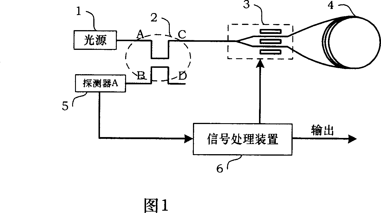
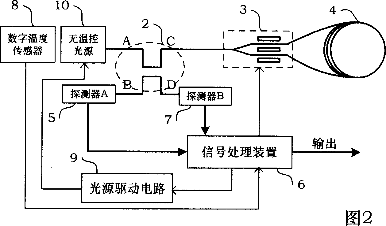
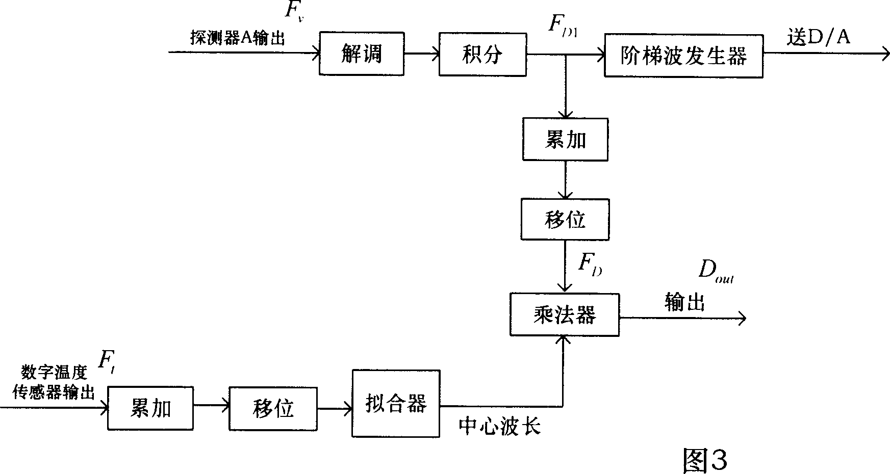
[0020] Please refer to Fig. 2, the present invention is a closed-loop fiber optic gyroscope without a temperature-controlled light source. On the basis of the existing fiber optic gyroscope, the general light source 1 is replaced by a non-temperature-controlled light source 10, and a digital temperature sensor 8 is used to collect The temperature of the core of the non-temperature-controlled light source 10 changes during operation, and a detector B7 is connected to the transmission D end of the coupler 2. The detector B7 is used to detect the change of the output optical power of the non-temperature-controlled light source 10 when the temperature changes. In order to control the change of the output angular velocity information of the fiber optic gyroscope caused by the temperature change of the non-temperature-controlled light source 10, on the one hand, the...


PUM


Abstract

A method for compensating output angular speed information of optical fiber gyroscope in temperature-control free and closed loop light source type includes applying regression analysis means to obtain adapting relation of central wavelength of outgoing light from temperature-control free light source to temperature then compensating optical gyroscope output angular speed information drift caused by temperature variation in utilizing optical gyroscope to output relevant relation value of central wavelength at outgoing light on temperature-control free light source.

Description

technical field [0001] The invention relates to a device and a compensation scheme for compensating angular velocity information output by a closed-loop optical fiber gyroscope without a temperature-controlled light source. Background technique [0002] The general interference fiber optic gyroscope is an instrument for measuring angular velocity. Its hardware consists of a light source 1, a coupler 2, a Y waveguide 3, an optical fiber ring 4, a detector 5 and a signal processing device 6 (see Figure 1). The measurement of the angular velocity of the interference fiber optic gyroscope is characterized by the size of the non-reciprocal phase difference caused by the two beams of light propagating in the fiber optic ring 4 in the rotation of the fiber optic gyroscope itself. Gyroscopes are devices sensitive to angular motion relative to inertial space. As an important inertial sensor, it is used to measure the attitude angle and angular velocity of the vehicle, and is the cor...

Claims


Application Information

Patent Timeline
Patent Type & Authority Applications(China)
IPC IPC(8): G01C19/72G01P9/00G01C19/64
Inventor 伊小素徐小斌宋凝芳金靖张春熹田海亭吕峰建
Owner BEIHANG UNIV
Why Eureka
Try Eureka