
Method, device, system for implementing clock synchronization, and distribution system

A clock synchronization and clock technology, which is used in time division multiplexing systems, synchronous signal speed/phase control, electrical components, etc. To achieve high-precision clock synchronization and other issues, to achieve the effect of reducing costs and reducing the impact of synchronization accuracy

Inactive Publication Date: 2007-05-09
SUPCON GRP +1
View PDF0 Cites 57 Cited by
  • Summary
  • Abstract
  • Description
  • Claims
  • Application Information

AI Technical Summary

Problems solved by technology

Therefore, the accuracy of the time stamp obtained between the CPU 12 and the MAC Controller 13 is not high, so that the accuracy of the clock synchronization achieved by this method cannot reach the sub-microsecond level
[0006] Therefore, the current clock synchronization technology has not yet achieved high-precision clock synchronization

Method used


Image

  • Method, device, system for implementing clock synchronization, and distribution system
  • Method, device, system for implementing clock synchronization, and distribution system
  • Method, device, system for implementing clock synchronization, and distribution system

Examples


Embodiment Construction

[0035]Below we will describe in detail the best implementation of the present invention with reference to the accompanying drawings. First of all, it should be pointed out that the meanings of the terms, words and claims used in the present invention should not be limited to their literal and ordinary meanings, but also include meanings and concepts that are consistent with the technology of the present invention. This is because It is up to us, as inventors, to define terms appropriately in order to best describe our inventions. Therefore, the configurations given in this specification and the accompanying drawings are only preferred implementations of the present invention, rather than enumerating all technical characteristics of the present invention. We need to recognize that there are various equivalents or modifications that could replace ours.

[0036] First, the overall technical solution of the method provided by the present invention is described. The method of the...


PUM


Abstract

The method includes that: obtains the local sending and receiving time stamp of the first data pack between the medium access controller and the physical layer receiver-sender; according to this local sending and receiving time stamp, calculates the error of the counting value of the clock counter and corrects this error. The invention also offers a device, system and distributed system to realize the clock synchronization. In this invention, the point to obtain the time stamp is between the medium access controller and the physical layer receiver-sender. This time stamp presents a more accurate parameter for the late process. The error is corrected more appropriately and the precision of the clock synchronization is raised.

Description

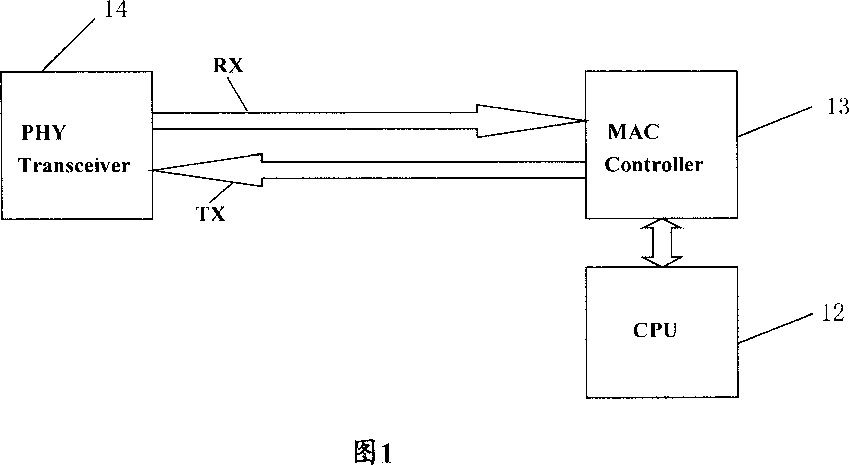
technical field [0001] The invention relates to distributed control technology, in particular to clock synchronization technology. Background technique [0002] In distributed systems such as industrial automation, motion control, power or telecommunications, the synchronization technology of real-time clocks has a wide range of applications. [0003] FIG. 1 is a schematic structural diagram of a current clock synchronization system. As shown in Figure 1, after CPU12 writes data packet into the cache memory of MAC (Media Access Control, media access control) Controller (controller) 13, order MAC Controller13 to send data packet again, after MAC Controller13 receives order, according to the Select the appropriate time to send the data packet to the PHY (Physical Layer Device, physical layer device) Transceiver (transceiver) 14. After the PHY Transceiver 14 completes the signal conversion, the data packet is sent to the network. [0004] In order to realize clock synchroniza...

Claims


Application Information

Patent Timeline
Patent Type & Authority Applications(China)
IPC IPC(8): H04L7/04
CPCH04J3/0697
Inventor 黄文君遇彬靳旭哲胡斌
Owner SUPCON GRP
Learn More