Implantable vision prosthesis

A visual prosthesis and prosthetic eye technology, applied in the field of visual prosthesis, can solve the problems that the single-stimulus electrode array is not conducive to fully utilizing the effective area of ​​the visual cortex, reducing the acceptability of visual prosthesis, and limiting the visual field of visual prosthesis. Achieve the effects of avoiding craniotomy, increasing spatial resolution, and increasing the field of view

Active Publication Date: 2007-05-16
上海华实投资有限公司
View PDF1 Cites 35 Cited by
  • Summary
  • Abstract
  • Description
  • Claims
  • Application Information

AI Technical Summary

Problems solved by technology

This method not only limits the field of view of the visual prosthesis functionally, but also the bulky and unsightly external camera system placed on the patient's face and the computer system placed on the waist greatly reduce the acceptance of the visual prosthesis by the patient.
In addition, the design and stimulation scheme of its single-stimulation electrode array are not conducive to making full use of the effective area of ​​the visual cortex, making the visual range smaller

Method used


Image

  • Implantable vision prosthesis
  • Implantable vision prosthesis
  • Implantable vision prosthesis

Examples


Embodiment Construction

[0018] The embodiments of the present invention are described in detail below in conjunction with the accompanying drawings: this embodiment is implemented on the premise of the technical solution of the present invention, and detailed implementation methods and specific operating procedures are provided, but the protection scope of the present invention is not limited to the following the described embodiment.

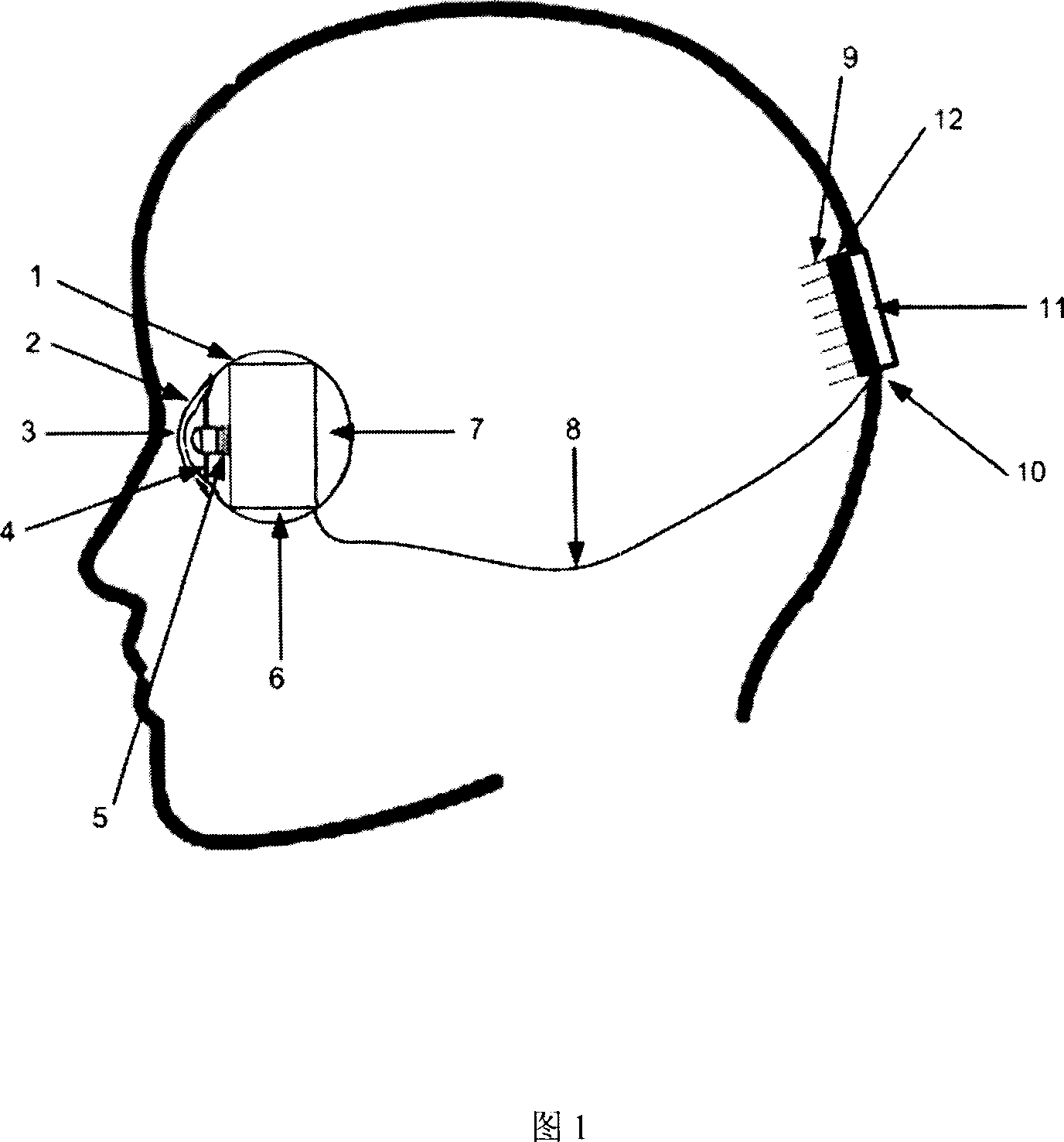
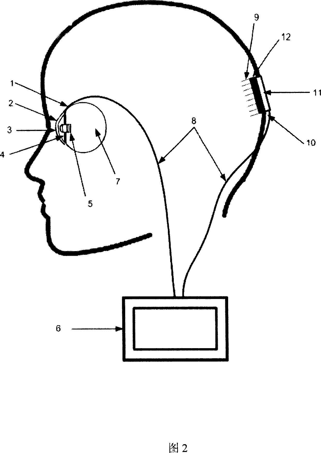
[0019] As shown in FIG. 1 and FIG. 2 , this embodiment includes: a micro-camera prosthetic eye 1 and a needle-type micro-electrode array 10 that can be implanted in the orbit. The micro-camera prosthetic eye 1 that can be implanted in the eye orbit images an object and converts the image signal into an electrical signal, and the electrical signal is encoded into a visual stimulation signal and then transmitted to the needle microelectrode array 10 to stimulate the visual cortex.

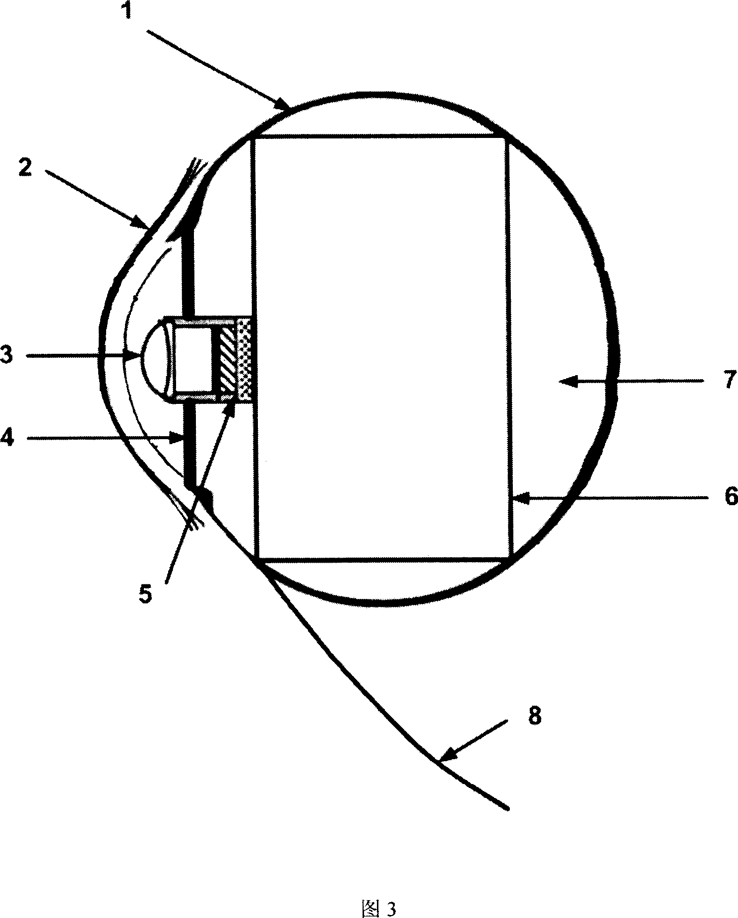
[0020] The micro-camera prosthetic eye 1 that can be implanted in the orbit includes: a ...


PUM


Abstract

The invention relates to a vision artificial element as medical tool, wherein it comprises that micro camera false eye and needle micro electrode array which can be planted into orbit; said micro camera false eye comprises solar energy battery board or charge device, micro optical lens group, photoelectric converter, signal processing converter, false eye base, and false eye sheet; the solar-energy battery board or charge device, micro optical lens group, photoelectric converter and signal processing converter are packed into false eye base; the signal processing converter is outside the false eye base; the micro camera false eye is planted into the orbit; the needle micro electrode array comprises base, micro electrode, inner wire, interface base, fixing hole, wire, and fixing plate; the fixing plate is fixed on the skull; the micro electrode via the drill hole of skull enters into vision layer; the vision electric signal via wire is transmitted into micro electrode array. The invention can improve the spatial accuracy of false eye.

Description

technical field [0001] The invention relates to a device in the technical field of medical instruments, in particular to an implantable visual prosthesis capable of partially restoring sight to a blind person. Background technique [0002] The human visual system obtains visual perception through the imaging of external objects by the eye optical system, the processing of image information by the visual nervous system, and the reprocessing of visual information by the visual center. However, some diseases, such as retinitis pigmentosa, age-related macular degeneration, and eye damage caused by trauma, often lead to loss of visual function, and it is currently impossible to restore visual function through conventional drug or surgical treatment. In fact, the loss of function of any component on the visual channel will cause the loss of function of the entire visual system. According to the working principle of the visual system, bionics are used to process and transform the ...

Claims


Application Information

Patent Timeline
Patent Type & Authority Applications(China)
IPC IPC(8): A61F9/08A61F2/14A61N1/05A61N1/08
Inventor 任秋实周传清
Owner 上海华实投资有限公司
Why Eureka
Try Eureka