Process for rolling taper pipe thread on thin-wall metal pipe fitting

A technology of metal pipe fittings and tapered pipe threads, which is applied in the field of forming rollers to process external threads, to achieve the effects of easy removal, convenient operation, and reduced labor intensity

Inactive Publication Date: 2007-05-16
李淑珍
View PDF0 Cites 10 Cited by
  • Summary
  • Abstract
  • Description
  • Claims
  • Application Information

AI Technical Summary

Problems solved by technology

[0004] The purpose of the present invention is to set up a pre-tightening counter pressure mechanism in the tube to resist the deformation of the thin-walled pipe.

Method used


Image

  • Process for rolling taper pipe thread on thin-wall metal pipe fitting

Examples


Embodiment Construction

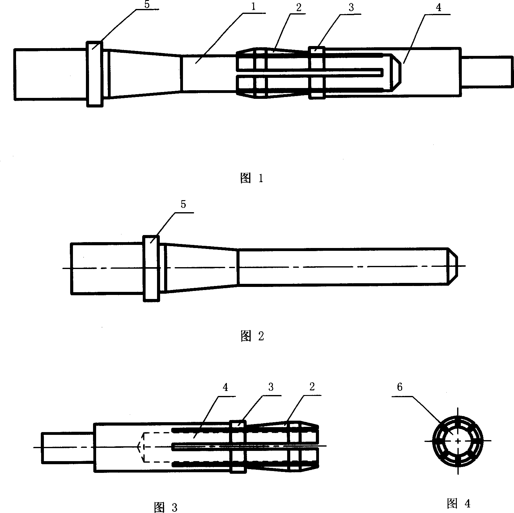
[0018] As shown in Figures 1 to 4. A process method for rolling tapered pipe threads on thin-walled metal pipe fittings. The main process is to use a combined tooling to complete on a well-known thread rolling machine, and it is characterized by comprising the following steps:

[0019] (1) Put the tensioning sleeve 4 into the clamping body of the machine tool, and then set the pipe to be processed on the end of the tensioning sleeve with the tapered head (2),

[0020] (2) Load the mandrel 1 into the workpiece to be processed, and at the same time into the middle hole 6 of the tensioning sleeve, clamp it,

[0021] (3) Process taper pipe threads according to process requirements.

[0022] The tensioning sleeve 4 and the mandrel 1 constitute a combined tooling. The tensioning sleeve 4 is a back pressure mechanism, which is characterized in that the rebound force increases with the increase of the rolling force, so as to keep the pipe fittings from being deformed. When the rolli...


PUM


Abstract

The invention relates to a method for rolling taper tube screw on thin-wall metal tube, wherein it is characterized in that: based on present rolling machine, it uses spindle and expanding sheath to fix the metal tube, then rolling. The invention inserts spindle in / out the expanding sheath to form compress / unload device to meet the support and unload demand of metal tube. The invention has simple structure and easy operation.

Description

technical field [0001] The invention relates to processing external threads with forming rollers, in particular to a process method for rolling taper pipe threads on thin-walled metal pipes. Background technique [0002] Copper and stainless steel are softer and have lower strength, and it is very difficult to directly roll tapered pipe threads at both ends of their thin pipe fittings. Deformation is the biggest problem. Deformation will cause defects such as non-standard threads and lack of thread meat. If a mandrel is inserted into the pipe for support in advance, it is difficult to extract the mandrel after rolling into a tapered pipe thread. This method is not feasible in mass production, so it can only be used for rolling cylindrical pipe threads. [0003] It can be seen that, for thin-walled metal pipes, how to roll them into standard tapered pipe threads has become the key to this technical field. The industry generally pays attention to solving this difficulty by a...

Claims


Application Information

Patent Timeline
Patent Type & Authority Applications(China)
IPC IPC(8): B21H3/04B23G7/00B23G1/44B23Q3/00B23Q27/00
Inventor 李淑珍
Owner 李淑珍
Why Eureka
Try Eureka