

Multiplex fibre optic interferometer and nesting constructing method of the same
A fiber optic interferometer and multiplexing technology, which is applied in the direction of using optical devices to transmit sensing components, optical devices, instruments, etc., can solve the problems of complex structure and small number of multiplexing of fiber optic interferometers, and achieve easy implementation, The cost is low and the effect of arraying is realized
- Summary
- Abstract
- Description
- Claims
- Application Information
AI Technical Summary
Problems solved by technology
Method used
Image


Examples
Embodiment 1
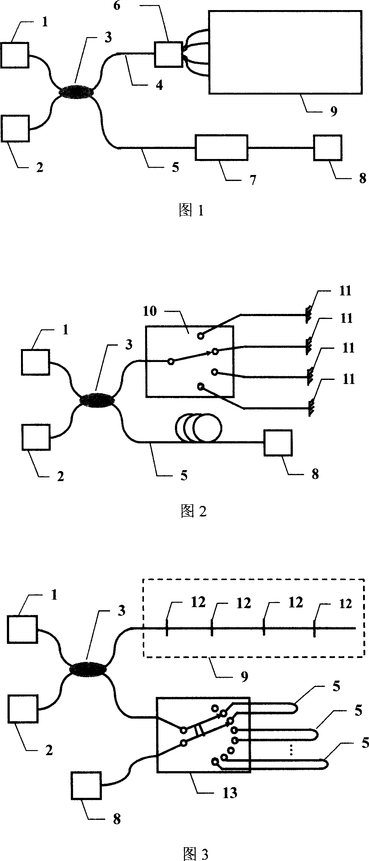
[0038] In conjunction with FIG. 1 , this embodiment includes a wide-spectrum light source 1 and a photodetector 2. The broadband light source 1 and the photodetector 2 are connected to the two optical fiber input ends of the optical fiber 2×2 coupler 3, and the optical fiber 2×2 coupler 3 The two optical fiber output ends are connected to the optical fiber splitter 6 and the optical path step accumulation type optical delay device 7 through single-mode optical fibers 4 and 5, and the optical path step accumulation type optical delay device 7 is connected to the continuously variable optical delay device 8, and the optical fiber splitter 6 A nested and multiplexed fiber interferometer array 9 is connected. Among them, the optical fiber 2×2 coupler 3 is a 3dB optical fiber 2×2 coupler; the optical fiber splitter is a single-mode optical fiber jumper; and the optical path step accumulation type optical delay device is a single-mode optical fiber jumper.
Embodiment 2
[0039] Embodiment 2: A scheme for a parallel multiplexed fiber optic interferometer constructed with a 1×4 fiber optic switch.
[0040] 2, this embodiment includes a wide-spectrum light source 1, a photodetector 2, a 3dB optical fiber 2×2 coupler 3, a reference arm single-mode connecting optical fiber 5, a continuously variable optical delay device 7, a 1×4 optical fiber switch 10 and Fiber end reflector 11, light source 1 and detector 2 are connected to two fiber input ends of 3dB single-mode fiber 2×2 coupler 3, and fiber output ends are respectively connected to 1×4 fiber switch 6 and continuously variable optical delay line 8 The function of the 1×4 optical fiber switch 6 is to realize the connection of different interferometers by switching the optical path, and at the same time cooperate with the optical path scanning in the continuously variable optical delay line 8 to obtain different white light interference fringes and realize the nested complex of optical fiber inter...
Embodiment 3
[0041] Embodiment 3: A series multiplexing interferometer solution composed of 2×8 optical fiber switches.
[0042] In conjunction with Fig. 3, the wide-spectrum light source 1, photodetector 2, 3dB optical fiber 2×2 coupler 3 and continuously variable optical delay line 8 in this embodiment are the same as those in Fig. 2, except that the 2×8 optical fiber The switch 13 and the single-mode optical fiber 5 of different lengths connected to the reference arm are composed of an optical path step accumulation type optical delay line and a reflective surface 12 . In addition, the structure of the nested fiber interferometer is changed from a parallel connection type to a serial connection type in which the fiber interferometers are connected end to end. When the fiber optic interferometer is working, the measurement beam enters an array connected in series by four fiber optic interferometers (fiber optic sensors), forming a series of reflection measurement signal lights with diffe...
PUM
 Abstract
Description
Claims
Application Information