Photography system for welding process of compound heat reservoir in carbon dioxide laser-melting argon-arc welding

A carbon dioxide, composite heat source technology, applied in photography, lasers, welding equipment, etc., can solve problems such as time-consuming, inability to guarantee, and lack of flexibility, and achieve the effect of avoiding damage

Inactive Publication Date: 2007-05-16
SHANGHAI JIAO TONG UNIV
View PDF0 Cites 15 Cited by
  • Summary
  • Abstract
  • Description
  • Claims
  • Application Information

AI Technical Summary

Problems solved by technology

However, due to the use of a fixed power He-Ne laser, the high-power carbon dioxide laser-MIG welding composite heat source welding process that requires multiple transformations for laser power parameters and MIG welding specifications is not flexible enough to ensure full Attenuation effect of laser on plasma and arc light when range parameters are changed
The built optical system requires the beam expander, imaging objective lens, pinhole diaphragm, interference filter, and lens to be strictly coaxial, and the optical components are placed relatively far away. It takes a lot of time to install and adjust the focal length, resulting in non-professional difficult to use
In addition, the pinhole diaphragm mainly performs neutral filtering in the optical system, and attenuates the arc light and the laser to the same degree to avoid overexposure, but the adjustment range of the pinhole diaphragm is very small. very inconvenient
Therefore, it cannot be applied to the research of high-power carbon dioxide laser-argon arc welding composite heat source welding process

Method used


Image

  • Photography system for welding process of compound heat reservoir in carbon dioxide laser-melting argon-arc welding

Examples


Embodiment Construction

[0017] The embodiments of the present invention will be described in detail below with reference to the drawings: this embodiment is implemented on the premise of the technical solution of the present invention, and detailed implementation manners and processes are given, but the scope of protection of the present invention is not limited to the following implementations example.

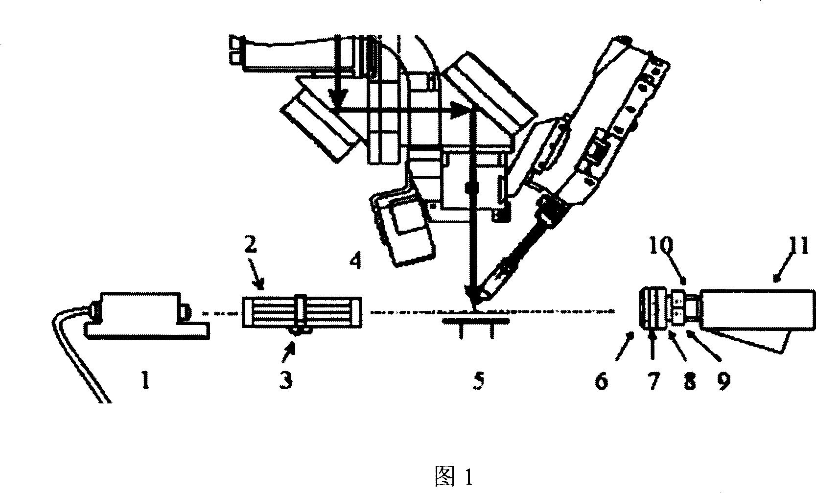
[0018] As shown in Figure 1, this embodiment includes: a semiconductor laser 1, a beam expander 2, a three-dimensional optical adjustment frame 3, a multilayer ultraviolet antireflection film 6, a circular polarizer combination 7, an interference filter 8, a metal threaded interface lens The ring, the photographic lens 9, the adapter 10 and the camera 11. In Figure 1, the carbon dioxide laser-melting argon arc welding compound torch 4 and the workpiece position 5 are experimental facilities.

[0019] Start the semiconductor laser 1, adjust the power to 10mw, make the emitted red laser incident on the mi...


PUM


Abstract

This invention relates to one carbon diode laser and metallic arc welding compound thermal source cameral system, which comprises semiconductor laser, floodlight tube, 3D optical adjust rack, multiple ultraviolet antireflection film, round bias vibration combination, intervene filter slices, cameral lens, transfer head and cameral machine, wherein, the former three parts form light source structure; later three parts form image forming structure; the cameral and transfer head form cameral structure; the light structure is at one side of cameral subject and the image forming structure and structure are connected through transfer head at other side of the subject.

Description

Technical field [0001] The invention relates to a photographing system in the field of welding technology, in particular to a carbon dioxide laser-melting argon arc welding composite heat source welding process photographing system. Background technique [0002] Welding arc phenomenon is characterized by high droplet transition frequency (usually tens of Hz), the droplet is enveloped in a strong arc light, and the droplet transition speed is fast (up to tens of meters per second). It is impossible to observe directly with the naked eye, and high-speed video or photography must be used for observation and research. At present, the high-speed photography system commonly used in welding process research is composed of a light source part, a beam expanding part, an imaging part and a photographing part. The light source part generally adopts a gas laser with a fixed power. After beam expansion, a spot of a certain size is formed. The beam passes through the melting area of ​​the weld...

Claims


Application Information

Patent Timeline
Patent Type & Authority Applications(China)
IPC IPC(8): G03B39/00G02B7/00H01S5/00B23K37/00H04N5/225
Inventor 王广伟蔡艳华学明黄坚李芳
Owner SHANGHAI JIAO TONG UNIV
Why Eureka
Try Eureka