Flue gas discharge continuous monitoring system based on image processing

A flue gas emission and image processing technology, applied in measurement devices, color/spectral property measurement, material analysis by optical means, etc., can solve the problems of high cost, limited scope of application, high cost and equipment loss, and achieve high sensitivity and accuracy, easy installation and maintenance, and strong function expansibility.

Inactive Publication Date: 2007-06-06
TIANJIN TELEVISION TECH INST
View PDF0 Cites 10 Cited by
  • Summary
  • Abstract
  • Description
  • Claims
  • Application Information

AI Technical Summary

Problems solved by technology

[0002] The existing continuous emission monitoring system (CEMS) is mainly based on front-end flue gas sensors to measure gas concentration, and most of them are built with imported sensor equipment as the core. , maintenance inconvenience
In terms of function, this type of system only outputs a single measurement data, but lacks the collection, display and storage of intuitive visual information of the smoke exhaust site, which is not convenient for comprehensive monitoring and management of sewage discharge
Some large-scale industrial enterprises install the continuous monitoring system of smoke emission and the video monitoring system of the smoke exhaust place at the same time, which is not only costly, but also because it is difficult to form an integrated and perfect monitoring management platform (the two systems have their own front-end and terminal), resulting in overall efficiency. underutilized
[0003] Some continuous monitoring solutions for flue gas emission based on image processing are only designed for black flue gas, and cannot effectively detect, identify and measure common colored flue gas such as red smoke (containing iron), yellow smoke (containing sulfur), and the scope of application is very limited
In addition, due to the use of preset fixed thresholds to judge the state of smoke emission, there is a lack of self-adaptation and effective fitting of the application situation and the external environment, making it difficult to avoid false positives and negative negatives caused by environmental factors

Method used


Image

  • Flue gas discharge continuous monitoring system based on image processing
  • Flue gas discharge continuous monitoring system based on image processing
  • Flue gas discharge continuous monitoring system based on image processing

Examples


Embodiment Construction

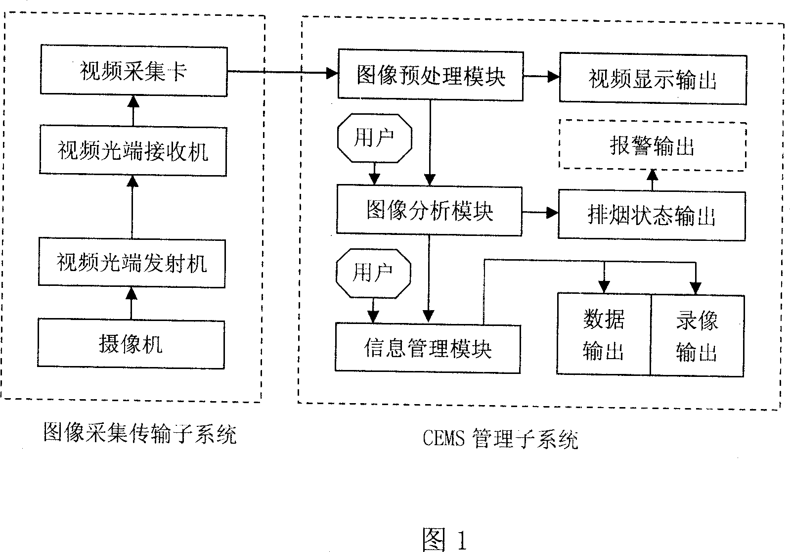
[0033] As shown in Figure 1, the analog video information collected by the front-end camera is transmitted to the local area through optical fiber communication, and converted into digital video information by the video acquisition card, that is, digital image sequence. In the following image preprocessing, the sequenced digital images are first converted from YUV format to RGB format, and then through filtering, sharpening, histogram transformation and other necessary processing to enhance their image quality, and then at a certain frame rate in the software displayed in real time on the interface.

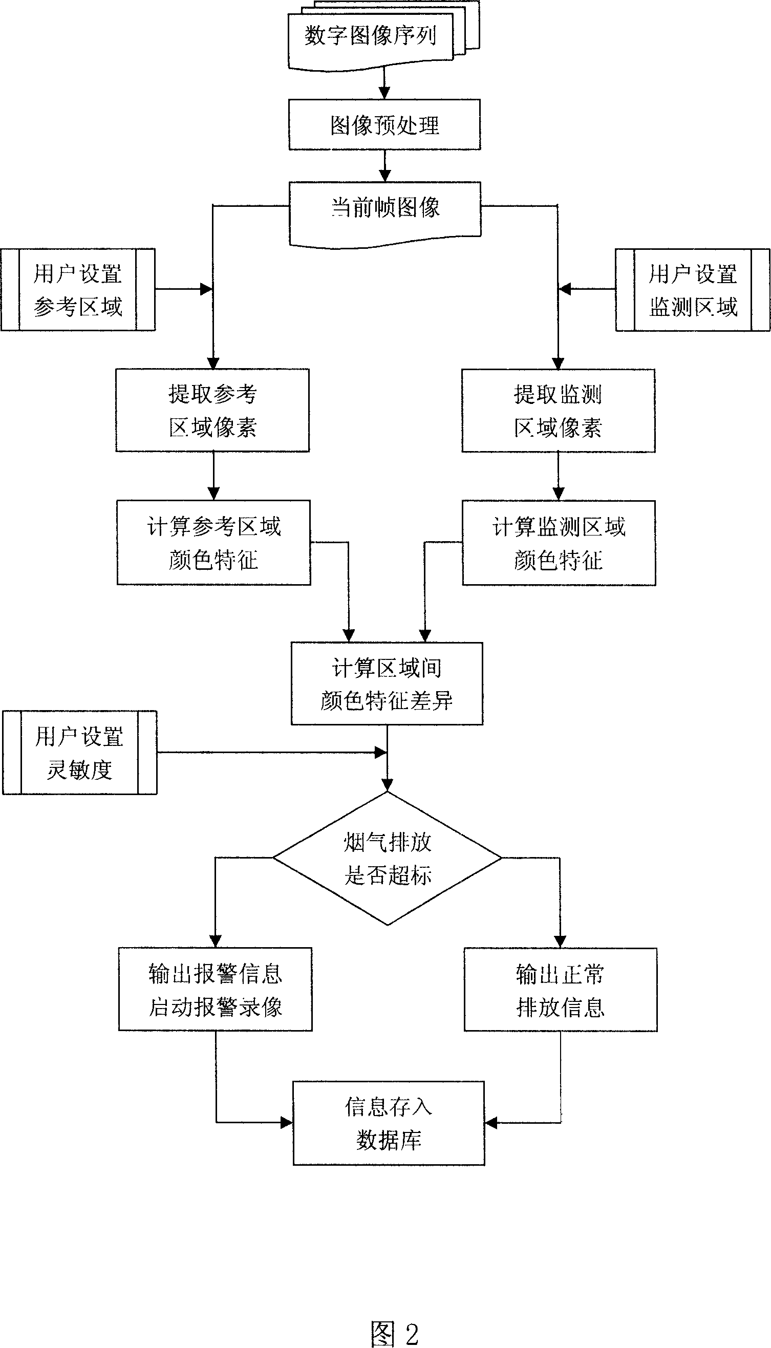
[0034] The subsequent image analysis module is the core of realizing the smoke monitoring function, and the processing steps are as follows:

[0035] 1. First obtain the reference area set by the user (specified as 8×8 pixel size) and the monitoring area;

[0036] 2. According to the reference area and monitoring area set by the user, the area positioning and pixel extraction ar...


PUM


Abstract

The invention relates to an observation system of the smoke discharging especially for the continuous observation system based on the figure treatment. The system includes the figure collection and transmitting subsystem, the CEMS management subsystem. The figure collecting management system includes the vidicon, the video optical transmitter, the video optical receiver and the video collecting card. The CEMS management subsystem includes the figure pretreatment module, the figure analyzing module and the information management module. It inspects the smoke discharging state by the non-contact video image treating method to be easy to install and maintenance. It has the low cost and strong maneuverability, function expansibility. Also it has the high sensitivity and accurate ratio. It can appraise of the smoke content and the user can select the reference region. It combines the smoke observation system and the video inspecting system and is controlled by the information management software.

Description

technical field [0001] The invention relates to a smoke discharge monitoring system, in particular to a continuous smoke discharge monitoring system based on image processing. technical background [0002] The existing continuous emission monitoring system (CEMS) is mainly based on front-end flue gas sensors to measure gas concentration, and most of them are built with imported sensor equipment as the core. , Inconvenient maintenance. In terms of function, this type of system only outputs a single measurement data, but lacks the collection, display and storage of intuitive visual information of the smoke exhaust site, which is not convenient for comprehensive monitoring and management of sewage discharge. Some large-scale industrial enterprises install the continuous monitoring system of smoke emission and the video monitoring system of the smoke exhaust place at the same time, which is not only costly, but also because it is difficult to form an integrated and perfect moni...

Claims


Application Information

Patent Timeline
Patent Type & Authority Applications(China)
IPC IPC(8): G01N21/84G01N21/25G08B21/00
Inventor 王东江李秀云符灵建郝强刘建辉刘哲闫影
Owner TIANJIN TELEVISION TECH INST
Why Eureka
Try Eureka