Transverse flux cylinder linear reluctance motor

A transverse flux, reluctance motor technology, applied in electrical components, electromechanical devices, electric components, etc., can solve the problems of eddy current loss, uneven distribution of the excitation magnetic field, etc., to reduce eddy current loss, improve material utilization and output thrust , the effect of reducing production costs

Inactive Publication Date: 2011-05-11
HARBIN INST OF TECH
View PDF2 Cites 1 Cited by
  • Summary
  • Abstract
  • Description
  • Claims
  • Application Information

AI Technical Summary

Problems solved by technology

[0003] In order to solve the problem of uneven distribution of the excitation magnetic field in the structure of the existing cylindrical hybrid linear reluctance motor and the eddy current loss caused by part of the magnetic flux path parallel to the axial direction of the motor, the present invention designs a transverse magnetic flux circle Cylindrical Linear Reluctance Motor

Method used


Image

  • Transverse flux cylinder linear reluctance motor
  • Transverse flux cylinder linear reluctance motor
  • Transverse flux cylinder linear reluctance motor

Examples


specific Embodiment approach 1

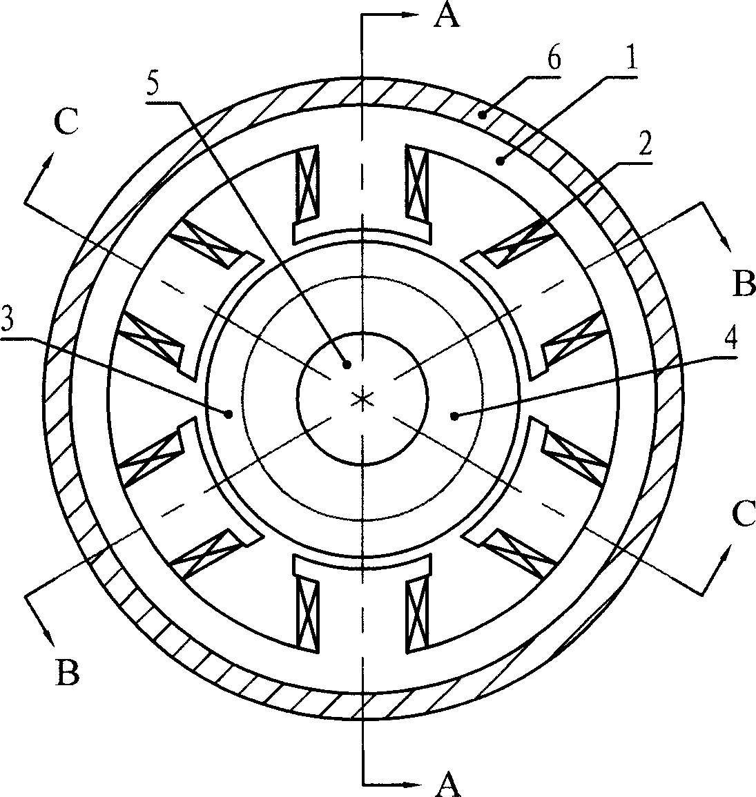
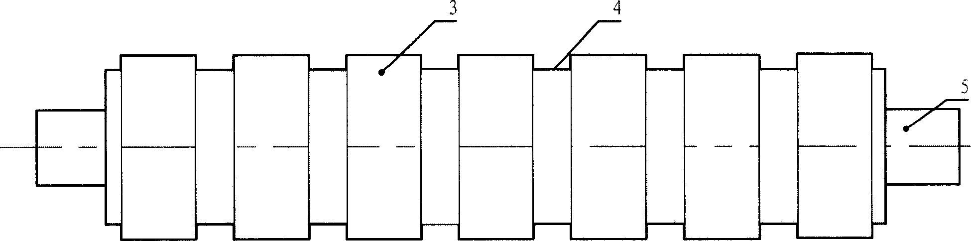
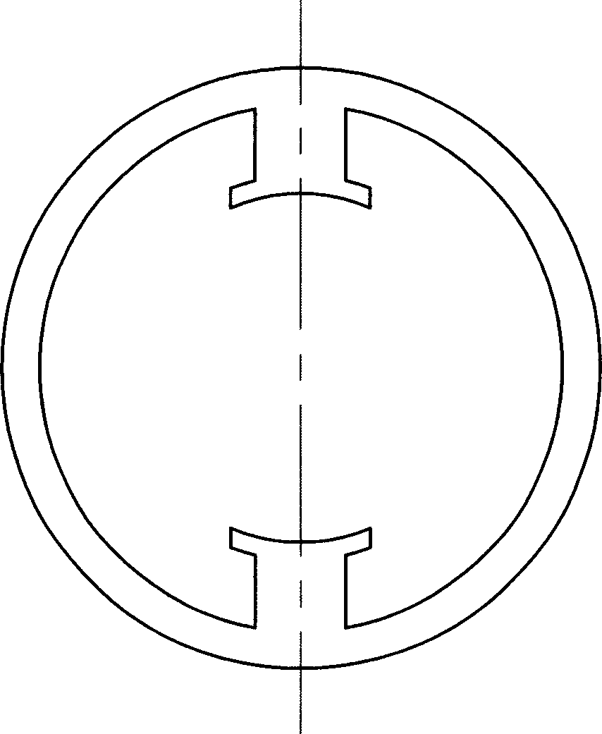
[0007] Specific embodiment one: see Figure 1 to Figure 8 , The transverse flux cylindrical linear reluctance motor of this embodiment is composed of a housing 6, an armature core 1, an armature winding 2, a mover tooth 3, a spacer ring 4, and a shaft 5. Each phase armature core 1 is fixed close to the inner wall of the casing 6, the spacer ring 4 and the mover teeth 3 are arranged alternately and fixedly sleeved on the shaft 5. There are 2n teeth on the armature core 1 of each phase, and n is a natural number; The armature core 1 is staggered in the circumferential direction by an angle of 360° / 2mn, where m is the number of phases of the motor; the coils of the armature winding 2 on the adjacent teeth of the armature core 1 of each phase have opposite winding directions, and the armature winding 2 of the same phase All the coils are connected in series.

[0008] This embodiment selects a three-phase motor, each phase armature core has 2 teeth, namely m=3, n=1, calculated accord...

specific Embodiment approach 2

[0011] Embodiment 2: The difference between the transverse flux cylindrical linear reluctance motor of this embodiment and Embodiment 1 is that both the armature core 1 and the mover teeth 3 are made of silicon steel sheets.

specific Embodiment approach 3

[0012] Specific embodiment 3: The transverse flux cylindrical linear reluctance motor of this embodiment is different from specific embodiments 1 or 2 in that the spacer ring 4 is made of magnetic material, and the outer diameter of the spacer ring 4 is smaller than that of the mover tooth 3. The outer diameter prevents the magnetic flux flowing out of the armature teeth from entering the spacer ring 4.


PUM


Abstract

A cylindrical linear magnetic resistance motor of horizontal magnetic flow relates to the motor field, which overcomes uneven distribution of exciter field in the prior cylindrical mixed horizontal magnetic motor structure and eddy current loss caused by the parallel of the part of flux path and the motor axial direction. The invention includes a casing (6), an armature core (1), an armature winding (2), a rotor tooth (3), a spaced ring (4) and a shaft (5), wherein each phase of armature core (1) is fixed closely to an internal wall of the casing (6), the rotor tooth (3) and the spaced ring (4) are fixed and jacketed in sequence on the shaft (5) in an alternative arrangement way, 2n numbers of teeth are set on each armature core (1), n is a natural number, each phase of armature core (1) is staggered by an angle of 360degrees / 2mn in the peripheral direction, m is a phase number of the motor, the coil winding direction of the armature winding (2) on adjacent tooth of each phase of armature core (1) is reverse, and all coils on the same phase armature winding (2) are series-connected together. The invention can replace the prior cylindrical mixed horizontal resistance motor.

Description

Technical field [0001] The invention relates to motor technology, in particular to a linear reluctance motor. Background technique [0002] The structure of the existing traditional cylindrical hybrid linear reluctance motor is shown in the attached drawings Picture 9 As shown, due to the influence of the iron core lamination gap, the excitation magnetic field generated by the permanent magnet is unevenly distributed along the axial direction. The farther away from the permanent magnet, the weaker the magnetic field, which limits the choice of the length of the iron core lamination and the material In addition, some of the flux paths are parallel to the motor axis, which will increase the eddy current loss of the motor. In addition, due to the large magnetic leakage in the slot, the electromagnetic thrust of the motor saturates faster, thereby reducing the performance-to-volume ratio of the motor. Summary of the invention [0003] In order to solve the problems of uneven field fi...

Claims


Application Information

Patent Timeline
Patent Type & Authority Patents(China)
IPC IPC(8): H02K41/03
Inventor 寇宝泉邵永实邝平健李立毅程树康
Owner HARBIN INST OF TECH
Why Eureka
Try Eureka