Method for detecting failure dapth of deep channel

A deep groove and depth technology, applied in the field of analysis and detection, can solve problems such as failure depth measurement and analysis, affecting cross-sectional view analysis, and difficulty in controlling collimation, so as to reduce analysis time, control and adjust easily, and reduce effect of time

Inactive Publication Date: 2007-06-13
SEMICON MFG INT (SHANGHAI) CORP +1
View PDF2 Cites 12 Cited by
  • Summary
  • Abstract
  • Description
  • Claims
  • Application Information

AI Technical Summary

Problems solved by technology

[0012] Secondly, the analysis performed by this prior art method is not easy to succeed
This is because the overall width of the deep groove is about 100nm, and the ion beam moves about 5nm at a time, so the phenomenon that the failure part is often cut off during cutting, so that the failure depth cannot be accurately measured and analyzed
Moreover, the overall depth of the deep groove is about 8um, and it is difficult to control the collimation of the ion beam during the downward cutting process, resulting in uneven cut sections, which affect the analysis of the cross-sectional views

Method used


Image

  • Method for detecting failure dapth of deep channel
  • Method for detecting failure dapth of deep channel
  • Method for detecting failure dapth of deep channel

Examples


Embodiment Construction

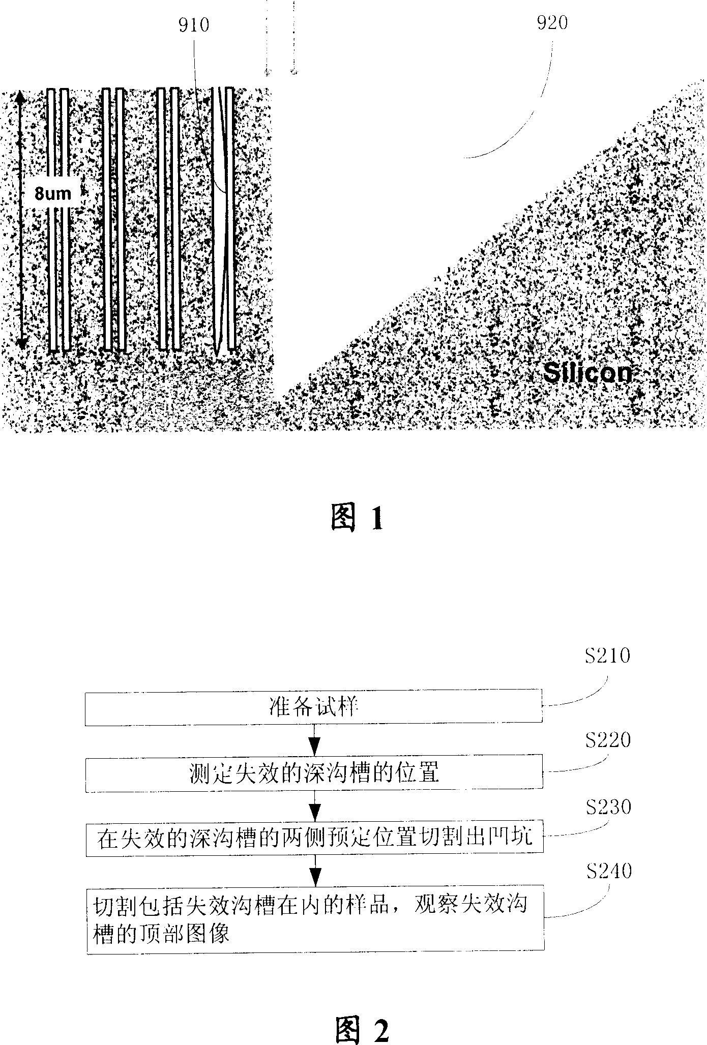
[0039] Please refer to FIG. 2 , which is a flow chart of the method for measuring the failure depth of a deep trench according to the present invention.

[0040] Step S210, sample preparation.

[0041] In the embodiment of the present invention, the size of the cut sample is about 10mm*10mm, and the surface treatment is performed on the sample test piece, so that the treatment described later can be performed on the deep trench layer.

[0042] Wherein, the surface treatment process can adopt chemical methods, such as soaking in 49% hydrofluoric acid HF for about 3 minutes, so that the surface of the test piece can be treated to the layer where the failure address can be located.

[0043] Step S220, put the sample into the FIB, rotate the FIB sample stage to a predetermined angle, so that the ion beam is perpendicular to the surface of the sample, and measure the position of the failed deep groove.

[0044] In an embodiment of the present invention, the predetermined angle is ...


PUM


Abstract

The method includes steps: preparing specimen, and obtaining position of ineffective deep groove in the sample; when rotating specimen stage for focusing ion beam to prearranged angle; the method uses ion beam perpendicular to surface of specimen to cut out drop pit at prearranged distance on one side of the deep groove; rotating specimen stage for focusing ion beam, the method uses ion beam inclined a prearranged angle with surface of the specimen to cut specimen including specimen with ineffective deep groove; and using electron beam inclined a prearranged angle with surface of the specimen to observing image at top of the ineffective deep groove. The invention saves time for analyzing ineffective depth of deep groove; raises analytical accuracy, and success ratio.

Description

technical field [0001] The invention relates to the analysis and detection technology in the integrated circuit manufacturing process, in particular to a method for measuring the failure depth of deep grooves. Background technique [0002] In recent years, with the development of semiconductor manufacturing process, cross-sectional structure has more and more influence on the yield and reliability of high-end devices. For example, in a deep trench (Deep Trench, DT), the shape and size of sidewalls are key factors affecting the performance of semiconductor devices. [0003] In order to improve the quality of the deep groove machining process, it is necessary to analyze the position of the failed deep groove and the failure depth of the failed groove, and feed back the data obtained from the analysis to the production department. This is because the processing of deep grooves usually needs to be divided into multiple stages, and the process conditions of each stage (such as g...

Claims


Application Information

Patent Timeline
Patent Type & Authority Applications(China)
IPC IPC(8): H01L21/66
Inventor 胡佑周
Owner SEMICON MFG INT (SHANGHAI) CORP
Why Eureka
Try Eureka