Method for machining spiral grooved-sided hobbing rear waved edge

A processing method and technology of face milling cutters, which are applied in the direction of milling cutters, metal processing equipment, milling machine equipment, etc., can solve the problem that the wave-blade face milling cutter cannot completely conform to the design drawings, and achieve the effect of eliminating the influence

Active Publication Date: 2007-06-20
AECC AVIATION POWER CO LTD
View PDF0 Cites 14 Cited by
  • Summary
  • Abstract
  • Description
  • Claims
  • Application Information

AI Technical Summary

Problems solved by technology

Due to the failure to solve the above three problems, the back wave edge face milling cutters manufactured in the past have not been able to fully meet the requirements of the design drawings.

Method used


Image

  • Method for machining spiral grooved-sided hobbing rear waved edge

Examples


example 1

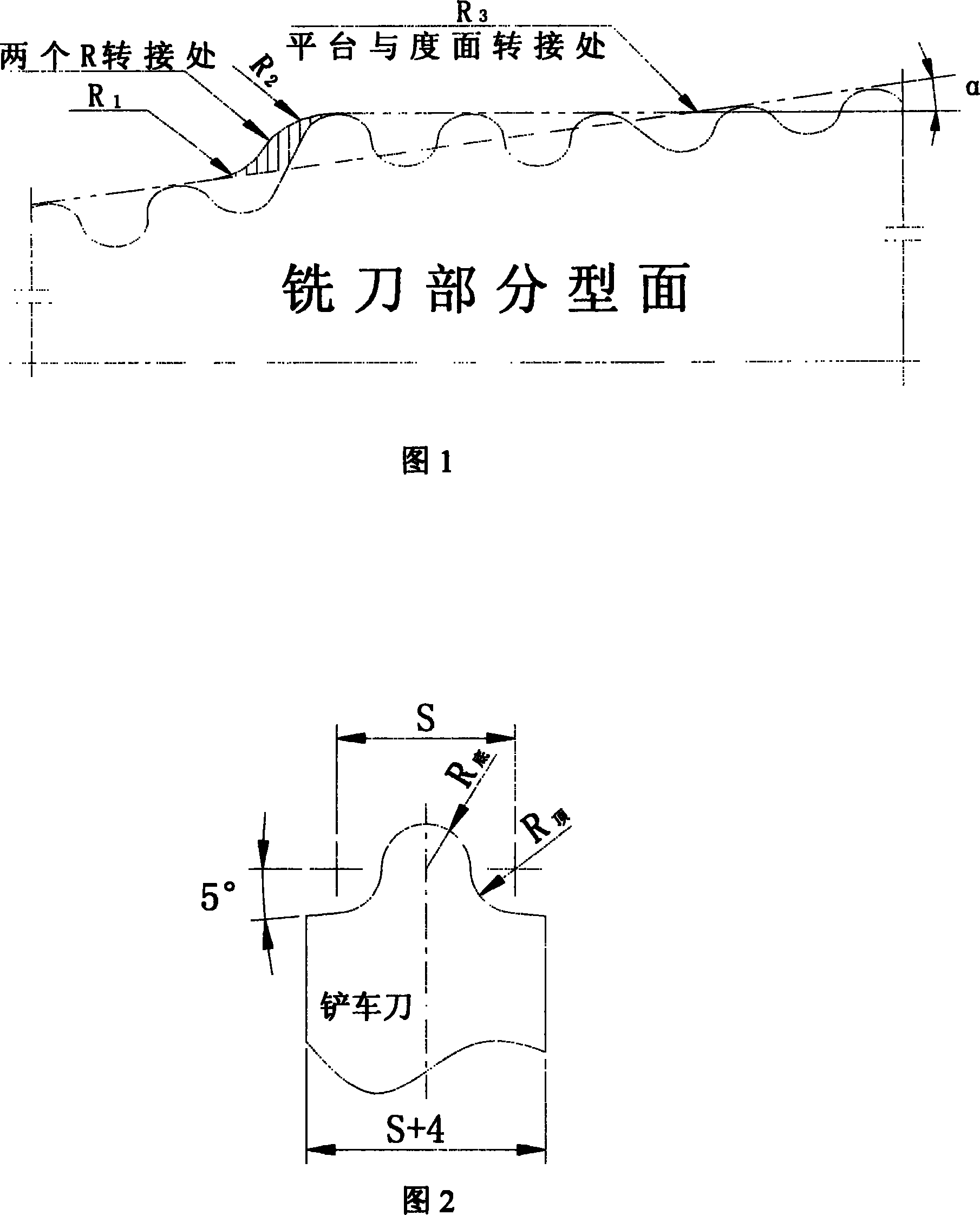
[0039] The number of teeth of the milling cutter is Z=16, the helix angle β=25°, the average diameter of the milling cutter to be processed is D=142.94, and the shoveling amount of the cutter tooth is K=6. The rear wave edge moves to the right, the pitch S=8, the bottom R of the rear wave edge is R1.8, the R of the tooth top is R2.5, and the rear wave edges of adjacent teeth are staggered by 0.5mm along the milling cutter axis.

[0040] Steps:

[0041]1. Make a template according to the profile of the milling cutter to be processed, and install it on the corresponding part of the gear removal machine tool.

[0042] 2. Dressing the grinding wheel profile of the shoveling machine tool.

[0043] The forklift tool is made according to the tooth shape of the rear wave blade, in which the top R of the turning tool is the bottom R of the rear wave blade tooth 底 , both sides of the top R are smoothly transferred to half of the rear wave edge addendum R 顶 And it is tangent to the fi...

example 2

[0059] The number of teeth of the milling cutter is Z=16, the helix angle β=25°, the average diameter of the milling cutter to be processed is D=132.60, and the shoveling amount of the cutter tooth is K=6. The rear wave edge moves to the right, the pitch S=8, the bottom R of the rear wave edge is R1.8, the R of the tooth top is R2.5, and the rear wave edges of adjacent teeth are staggered by 0.5mm along the milling cutter axis.

[0060] Steps:

[0061] Change the differential hanging gear of the shovel gear machine to I 2 =55×60 / 62×39, and the rest of the operation steps are the same as Example 1.

example 3

[0063] The number of teeth of the milling cutter is Z=16, the helix angle β=25°, the average diameter of the milling cutter to be processed is D=146.02, and the shoveling amount of the cutter tooth is K=6.2. The rear wave edge moves to the right, the pitch S=8, the bottom R of the rear wave edge is R1.8, the R of the tooth top is R2.5, and the rear wave edges of adjacent teeth are staggered by 0.5mm along the milling cutter axis.

[0064] Steps:

[0065] Change the differential hanging gear of the shovel gear machine to I 2 =50×58 / 60×39, the actual K value is changed to: K 实际 = 6.2. The rest of the operation steps are the same as Example 1.


PUM


Abstract

A method for machining the waved back cutting edge of the milling cutter used to machine spirally slotted surface on workpiece includes such steps as installing a copying plate, trimming the machining surface of abrasive disc, arranging change gear, clamping the workpiece to be machined, aligning cutter, and grinding.

Description

technical field [0001] The invention belongs to the cutting tool manufacturing technology and relates to the improvement of the processing method of the rear wave edge type face milling cutter. Background technique [0002] When processing parts with large surfaces, if a milling cutter with a common shape is used for processing, since the contact area between the milling cutter and the processed part is too large, a large cutting resistance will be generated during the processing, and the vibration caused by this resistance cannot guarantee the quality of the parts. machining accuracy. This abnormal processing process is also easy to cause the fragmentation of the milling cutter, and even the cutting process cannot be performed. Therefore, when processing parts with large faces or difficult-to-machine materials, rear wave edge face milling cutters are often used. At this time, because the contact area between the milling cutter and the processed part is reduced, the cuttin...

Claims


Application Information

Patent Timeline
Patent Type & Authority Applications(China)
IPC IPC(8): B23P15/34B23B5/42B24B3/02
Inventor 郑超王挺杨克让王凡旺
Owner AECC AVIATION POWER CO LTD
Why Eureka
Try Eureka