
IC punching formation equipment

A technology of forming equipment and integrated circuits, which is applied in metal processing equipment, feeding devices, positioning devices, etc., can solve the problems of difficult to increase the overall speed of the system, long response time of cylinder action, low stability and reliability, etc. Reduced response time, short cycle times, good stability

Inactive Publication Date: 2007-06-27
TONGLING TRINITY TECH
View PDF0 Cites 11 Cited by
  • Summary
  • Abstract
  • Description
  • Claims
  • Application Information

AI Technical Summary

Problems solved by technology

[0005] The advantage of this kind of integrated circuit punching and forming equipment is that the structure is simple, but its disadvantage is that the four actions of separation detection, separation, adsorption device lifting and forward and backward movement are related in time sequence, and four different power sources are used. To drive, because the reaction time of the cylinder action is long, for the sake of safety, each action has a certain safety time. When the speed increases, the safety time of each independent action is reduced, and the reliability of the entire equipment is reduced. Therefore, the overall system It is difficult to increase the speed. At the same time, the action is completed under the cooperation of multiple power sources, which brings great difficulties to adjustment and control. Its stability and reliability are low, which seriously affects the improvement of production capacity.

Method used


Image

  • IC punching formation equipment
  • IC punching formation equipment
  • IC punching formation equipment

Examples


Embodiment Construction

[0027] The invention includes a driving device, a feeding device, a separating device and a discharging device.

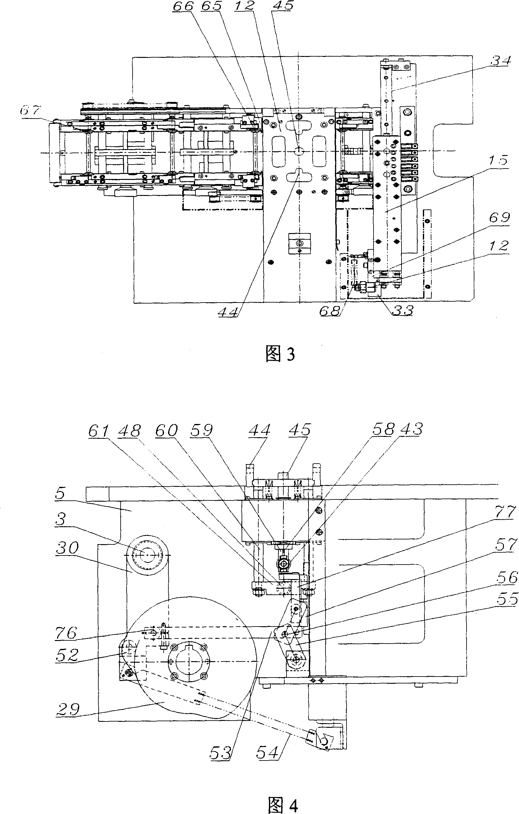
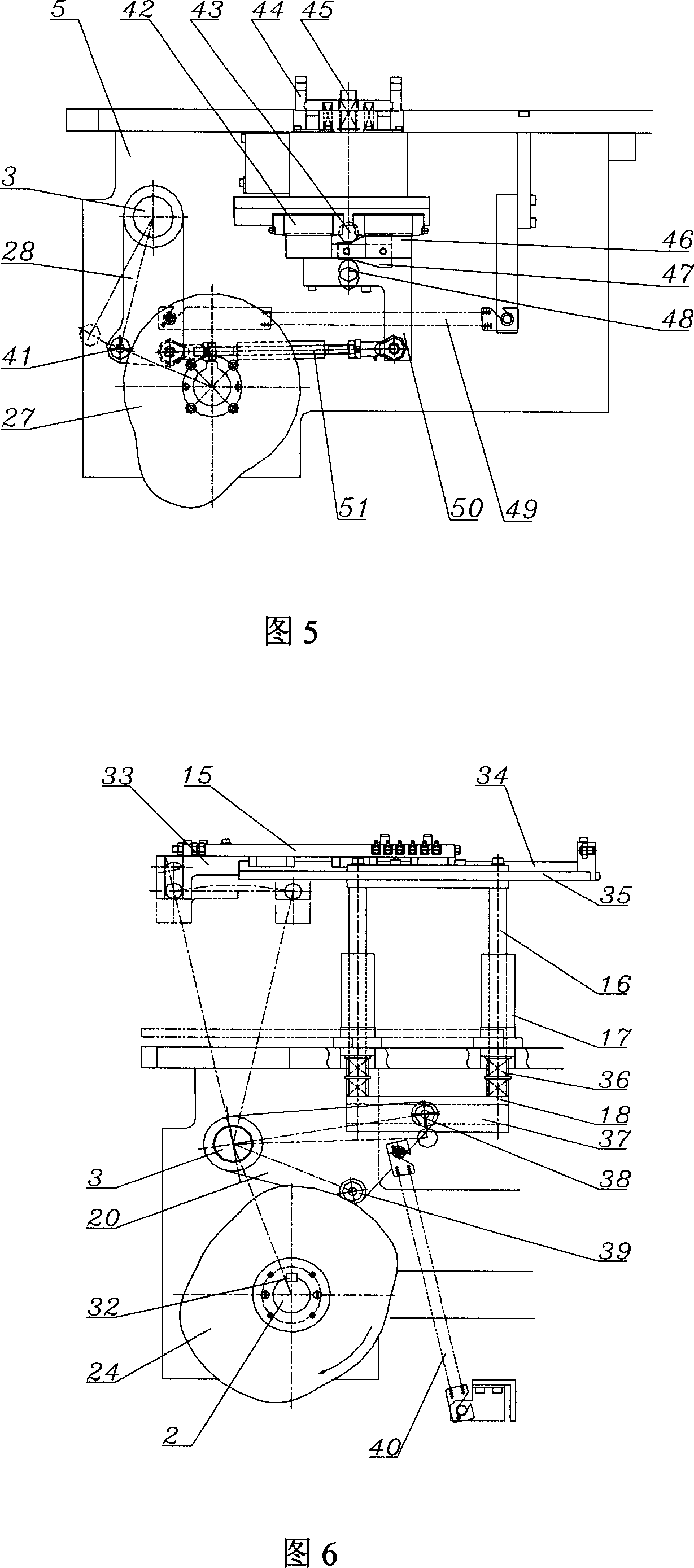
[0028] The drive device, as shown in FIG. 2 , includes a drive wheel 1 and a camshaft 2 connected to a frame 5 . The camshaft 2 is connected on the frame 5 by bearings 23 at both ends, and the transmission wheel 1 is fixedly connected to one end of the camshaft 2, and the transmission wheel 1 and the power source are connected by a synchronous belt 31 to realize transmission.

[0029] The feeding device is shown in Figure 2, which includes a feeding motor 6, a feeding roller 8, a pressing roller 67 and a pressing cylinder 7, and the pressing roller 67 and the feeding roller 8 are pressed against the lead frame under the action of the pressing cylinder 7. The feeding is driven by the feeding motor 6; the feeding detection device is composed of a detection sensor 10, a brake cylinder 11 and a brake block 65, and the detection sensor 10 is fixed on the detection plate...


PUM


Abstract

The IC punching formation equipment includes one feeder, one separator and one discharger. On the frame, there are cam shaft with fixed separation detecting cam, separating cam, vertical discharge cam and horizontal discharge cam; and oscillating arm shaft fixed to the cam shaft and with connected separation detecting oscillating arm, separating oscillating arm, vertical discharge oscillating arm and horizontal discharge oscillating arm. All the cams and all the oscillating arms cooperate to complete the separation detection, separation, discharge elevation and horizontal discharge moving of the lead frame separately. The present invention uses only one power source, and has high punching speed, high capacity and stable running.

Description

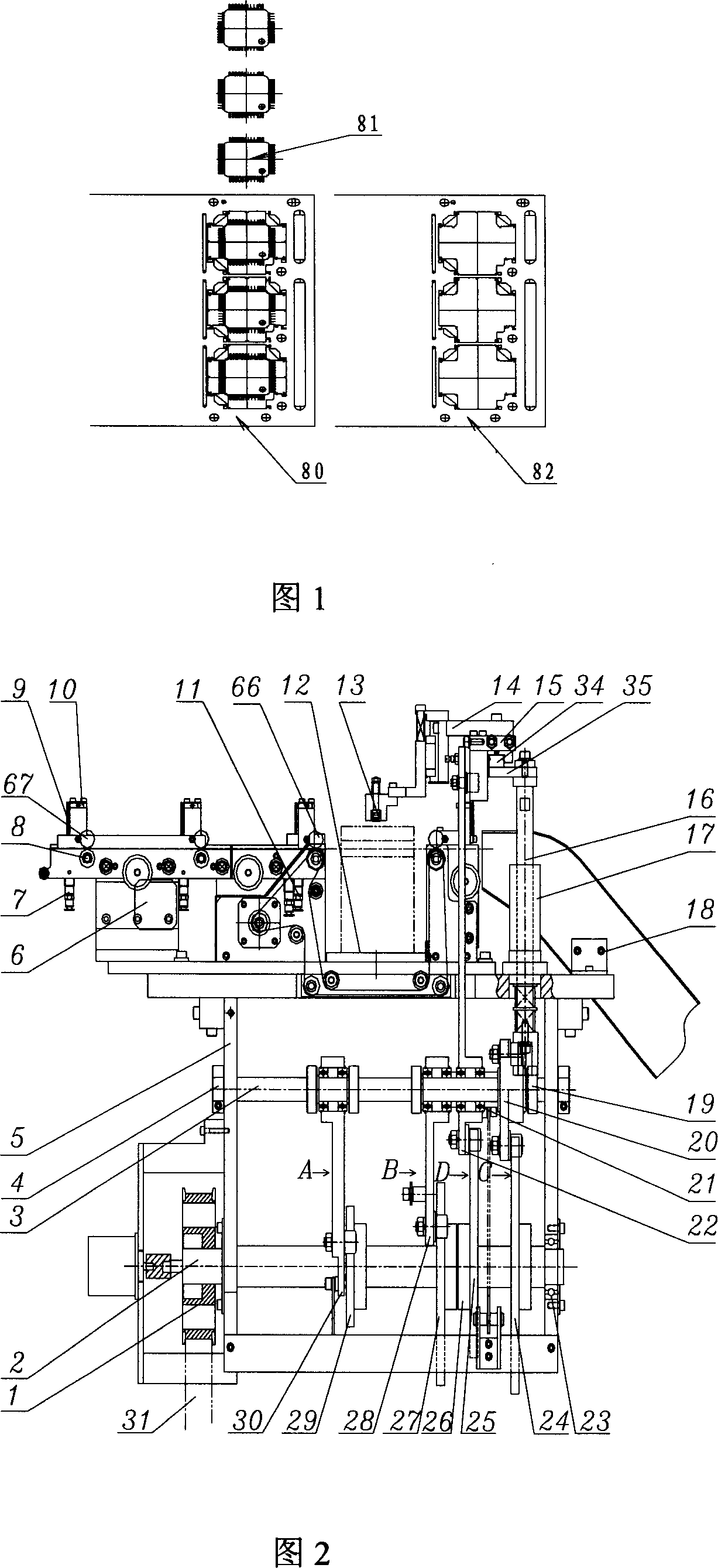
technical field [0001] The invention relates to a punching and forming equipment for separating integrated circuit lead frames. Background technique [0002] In the production of integrated circuits, as shown in Figure 1, the lead frame 80 is separated into products 81 and waste materials 82 on the punching and forming equipment. The action process generally includes separation detection, separation and discharge, and the discharge action includes the lifting and lowering of the adsorption device. Move back and forth for two actions. Separation generally uses a cylinder as a power to guide the separation mold to separate the product. Before separation, it is necessary to detect whether the lead frame is in place in the separation mold. Therefore, the separation mold needs to have two actions of separation detection and separation of the position of the lead frame. Independent cylinders are used as power to complete the action. The existing integrated circuit punching and f...

Claims


Application Information

Patent Timeline
Patent Type & Authority Applications(China)
IPC IPC(8): B21D28/02B21D43/00B21D45/00B21C51/00
Inventor 刘正龙
Owner TONGLING TRINITY TECH
Learn More