Method and its device for garbage burning and flyash incinerating treatment

A waste incineration fly ash and calcination treatment technology, which is applied in the field of environmental engineering, can solve the problems of PCDD/Fs secondary pollution, loss of fly ash and calcination harmless treatment, etc., to prevent resynthesis, save energy, and have good economic benefits Effect

Inactive Publication Date: 2007-06-27
DALIAN INST OF CHEM PHYSICS CHINESE ACAD OF SCI +1
View PDF0 Cites 14 Cited by
  • Summary
  • Abstract
  • Description
  • Claims
  • Application Information

AI Technical Summary

Problems solved by technology

[0004] Calcination is the most effective way to remove organic micro-pollutants in waste incineration fly ash, but the calcination process also requires strict technical control, otherwise a large amount of PCDD / Fs in fly ash will be thermally desorbed, and PCDD / Fs may occur Resynthesis, if the flue gas in the calcination process is directly discharged into the atmosphere without strict treatment, it will cause serious PCDD / Fs secondary pollution, thus losing the meaning of harmless treatment of fly ash calcination

Method used


Image

  • Method and its device for garbage burning and flyash incinerating treatment

Examples


Embodiment 1

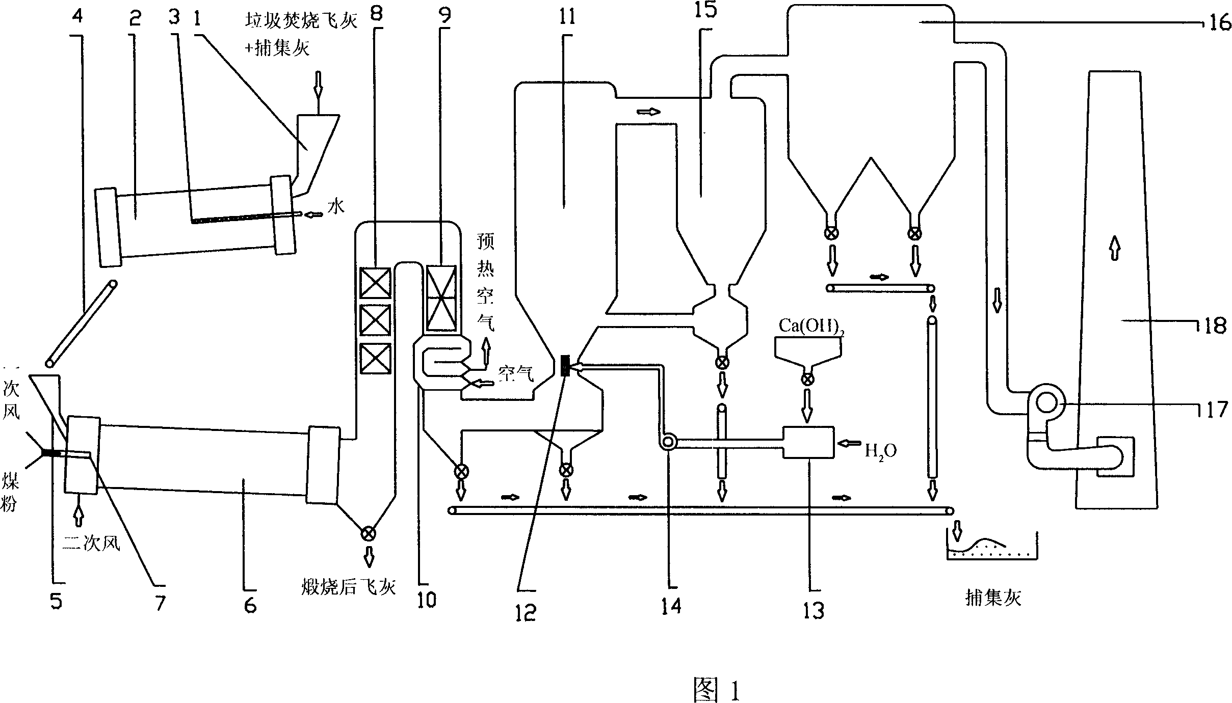
[0024] The waste incineration fly ash calcination treatment device is shown in Figure 1. The device includes: a drum granulator, a conveyor belt, a rotary calciner, a waste heat recovery system and a flue gas purification system. The rotary calciner is located behind the drum granulator, and a conveyor belt 4 is arranged between them. One end of the waste heat recovery system is connected to the rotary calciner, and the other end is connected to the flue gas purification system.

[0025] The drum granulator includes an ash hopper 1, a drum 2, and a water spray pipe 3. The ash hopper 1 and the water spray pipe 3 are arranged at the front end of the drum 2, and a conveyor belt 4 is provided below the rear end of the drum 2. .

[0026] Among them: there is a sealing baffle at the feed port of the drum granulator, and a semi-closed baffle at the discharge port to prevent fly ash from flying away.

[0027] The rotary calciner includes a feeding device 5, a burner 7, a secondary ai...

Embodiment 2

[0038] The difference from Example 1 is:

[0039] 1. Granulation stage: The fly ash stays in the drum granulator for 4±0.5 minutes, and the water content after granulation is 42+3%.

[0040] 2. Calcination stage: the temperature in the preheating zone is 200 - Preheat at 800°C for 7±1 minutes, after preheating at 800 - 1300°C (at 1100 - Calcination at 1200°C for 6 minutes, PCDD / Fs and other organic micro-pollutants in the fly ash can be completely decomposed) Stay in the high-temperature calcination zone for 12±1 minutes.

[0041] 3. Subsequent treatment stage: the flue gas temperature at the outlet of the air preheater is controlled at 225±5°C, and the lime injection rate is 1.0±0.1 g / standard cubic meter.

Embodiment 3

[0043] The difference from Example 1 is:

[0044] 1. Granulation stage: The fly ash stays in the drum granulator for 4.5±0.5 minutes, and the water content after granulation is 45±5%.

[0045] 2. Calcination stage: the preheating temperature is 200 - Preheat at 800°C for 8±1 minutes, after preheating, the temperature is 800 - 1200℃ (at 1000 - Calcined at 1100°C for 8 minutes, PCDD / Fs and other organic micro-pollutants in the fly ash can be completely decomposed) stay in the high temperature zone for 13±1 minutes.

[0046] 3. Subsequent treatment stage: the flue gas temperature at the outlet of the air preheater is controlled at 235±5°C, and the lime injection rate is 1.1±1 g / standard cubic meter.


PUM


Abstract

A process for treating the fly ash generated by incinerating garbage includes such steps as spray water onto fly ash, granulating, pre-heating, high-temp burning, recovering the afterheat from generated fume, cleaning the fume, and exhausting. Its apparatus is composed of drum-type granulating machine, conveying belt, rotary calcining furnace, afterheat recovering system, and fume cleaning system.

Description

technical field [0001] The invention belongs to the technical field of environmental engineering, and in particular relates to a method and a device for calcination treatment of waste incineration fly ash. Background technique [0002] Waste incineration has become an important way of waste disposal in my country. Although waste incineration has the advantages of reduction, recycling, and complete elimination of virus and microorganisms, many trace and ultra-trace organic micropollutants, such as dioxin-like (PCDD / Fs) polycyclic aromatic hydrocarbons, are also produced during the incineration process. (PAHs), polychlorinated biphenyls (PCBs) and polychlorinated naphthalenes (PCNs), etc. Among these pollutants, PCDD / Fs has high toxicity, serious pollution, carcinogenic, teratogenic, mutagenic and other toxic and side effects, which has aroused widespread concern. [0003] Only a small part of PCDD / Fs produced by waste incineration enters the atmosphere with flue gas, while ...

Claims


Application Information

Patent Timeline
IPC IPC(8): F23G5/02
CPCY02P80/15
Inventor 张海军倪余文陈吉平项光明朱善银陈革
Owner DALIAN INST OF CHEM PHYSICS CHINESE ACAD OF SCI
Why Eureka
Try Eureka