
Method for producing radio frequency identifying antenna and its antenna structure

A manufacturing method and a technology for identifying antennas, which are applied in the structural form of radiating elements, antennas, and antenna components, etc., and can solve problems such as larger component volume, increased resistance value, and reduced sensing distance.

Inactive Publication Date: 2007-06-27
IND TECH RES INST
View PDF2 Cites 5 Cited by
  • Summary
  • Abstract
  • Description
  • Claims
  • Application Information

AI Technical Summary

Problems solved by technology

[0004] In order to increase the efficiency of inductive coupling, the number of turns of the coil in the card module is usually increased to increase its inductance value, but this manufacturing method will increase the size of the component, increase the resistance value, multi-turn signal interference, and reduce the sensing distance or Problems such as poor resolution
[0005] Please refer to Japanese Patent Publication No. JP2002368525. In this patent application, the antenna is stacked in multiple layers, and a magnetic powder substrate such as magnesium iron is added to the center of the antenna to increase the inductance value. Although the method can increase the inductance value, it also increases the thickness of the component, and is not flexible at the same time. It has no substantial advantages and competitiveness in market applications.
[0006] Please refer to Japanese Patent Publication No. JP2000261230. The method of manufacturing the antenna in this patent application is similar to that of the above-mentioned patent. Its method is also to stack multi-layer antennas. The difference lies in the arrangement direction of the magnetic material and the arrangement direction of the metal lines. Similarly, although the thickness of the component can be reduced, it also leads to a limited increase in the inductance value

Method used


Image

  • Method for producing radio frequency identifying antenna and its antenna structure
  • Method for producing radio frequency identifying antenna and its antenna structure
  • Method for producing radio frequency identifying antenna and its antenna structure

Examples


Embodiment Construction

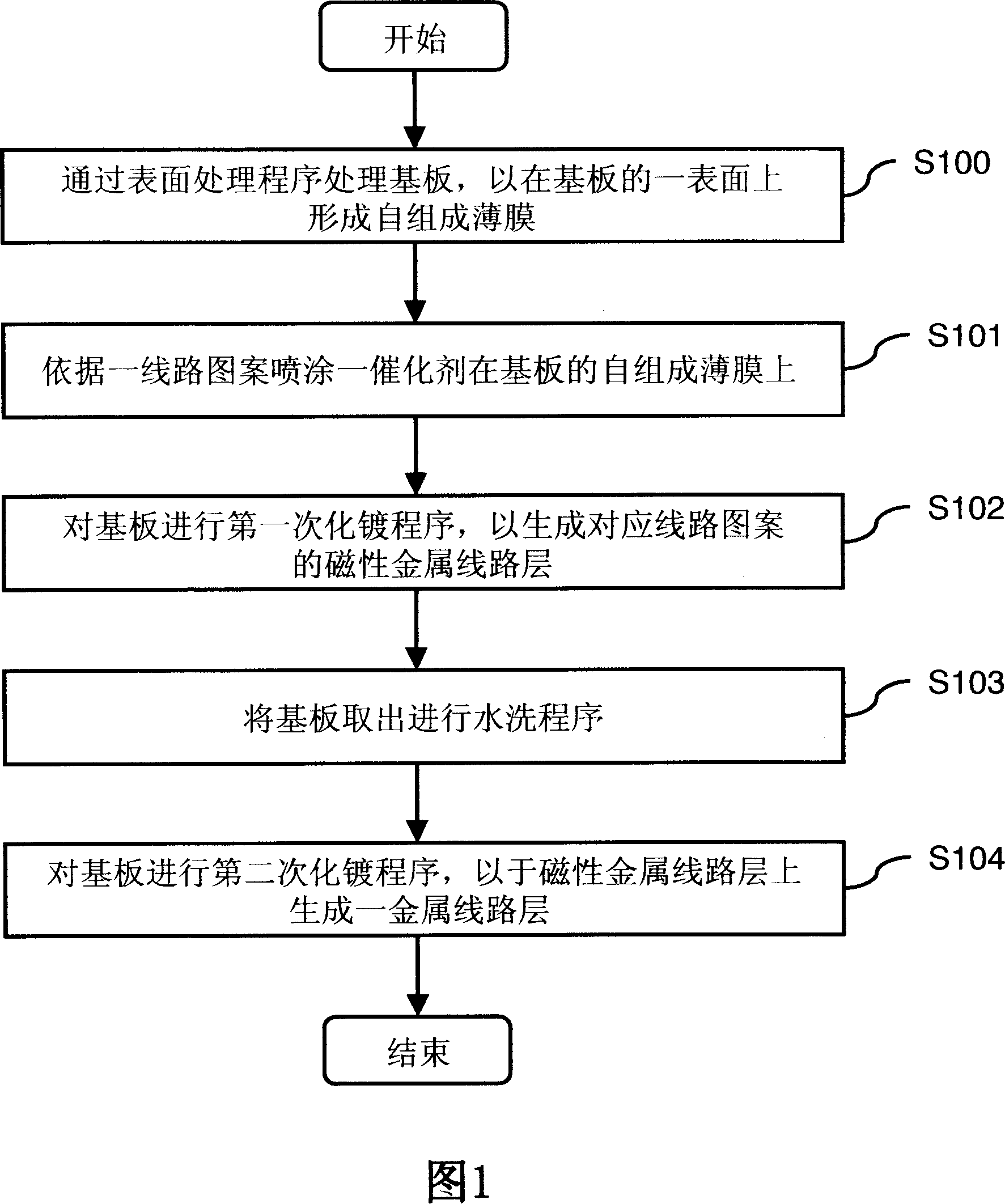
[0028] Please refer to FIG. 1, which is a flow chart of the manufacturing steps of the single-layer radio frequency identification antenna of the first embodiment of the present invention, including:

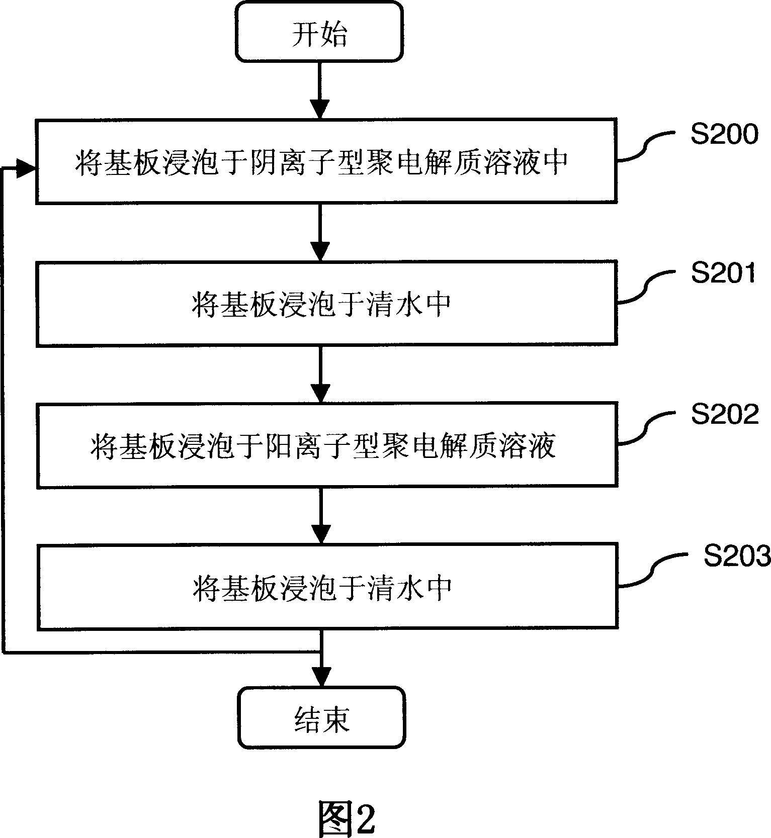
[0029] In step S100, first, the substrate is treated by a surface treatment program (for example, plasma treatment, ion beam treatment or ozone treatment) to form a self-assembly thin film (Self-Assembly) on a surface (for example, upper surface or lower surface) of the substrate. Membrane, SAM);

[0030] Step S101, spray a catalyst (for example, sodium tetrachloropalladate (Na 2 PdCl 4 ) solution and tetraammonia palladium dichloride (Pd(NH 3 ) 4 Cl 2 ) solution) on the self-composed thin film of the substrate, wherein the micro-droplet generation device uses an inkjet head or a dot array head (arrayer) to spray the catalyst on the substrate.

[0031] Step S102, performing the first electroless plating process on the substrate to generate a magnetic metal (for example, nic...


PUM


Abstract

This invention relates to a manufacturing method and a structure of radio RF identifying antennas, which connects one or many antennas to a plane or cubic structure by a surface process of a base plate and an ink spraying method to process antenna patterns and radio plating to let it have pliability and high inductance value.

Description

technical field [0001] The invention relates to an antenna manufacturing method and its antenna structure, in particular to a high inductance radio frequency identification (RFID) antenna manufacturing method and its antenna structure. Background technique [0002] Contactless radio frequency systems have been widely used in many industries today. In the future, every product from the company will have a non-contact radio frequency system on the product. This system will record in detail the relevant data of the upstream and downstream manufacturers of the product (for example, product specifications, materials or delivery dates, etc.) etc.), the data required for logistics (for example, distribution network or inventory information, etc.), the information required by consumers (such as price, conformity marks, usage methods or maintenance pipelines, etc.), and these information will vary due to different The demand side has different access rights. [0003] The architectu...

Claims


Application Information

Patent Timeline
IPC IPC(8): H01Q1/00H01Q1/38H05K3/00H05K3/14
Inventor 王仲伟何勇国杨明桓吴嘉琪郑兆凯
Owner IND TECH RES INST
Learn More