Eureka AIR delivers breakthrough ideas for toughest innovation challenges, trusted by R&D personnel around the world.

Method and tunnel drilling machine or selective cutting machine for driving a tunnel borehole

A technology for drilling and excavating machines, used in tunnels, earth-moving drilling, mining equipment, etc., can solve problems such as increased wear and tear, and achieve the effect of reducing downtime and friction

Inactive Publication Date: 2007-06-27
WIRTH MASCH UND BOHRGERATE FAB GMBH
View PDF0 Cites 6 Cited by
  • Summary
  • Abstract
  • Description
  • Claims
  • Application Information

AI Technical Summary

Problems solved by technology

But because there is always a large amount of drilled material that has been cut in the drill head space, it is also in contact with the moving parts of the drill head, which significantly increases the wear of these parts

Method used


Image

  • Method and tunnel drilling machine or selective cutting machine for driving a tunnel borehole

Examples


Embodiment Construction

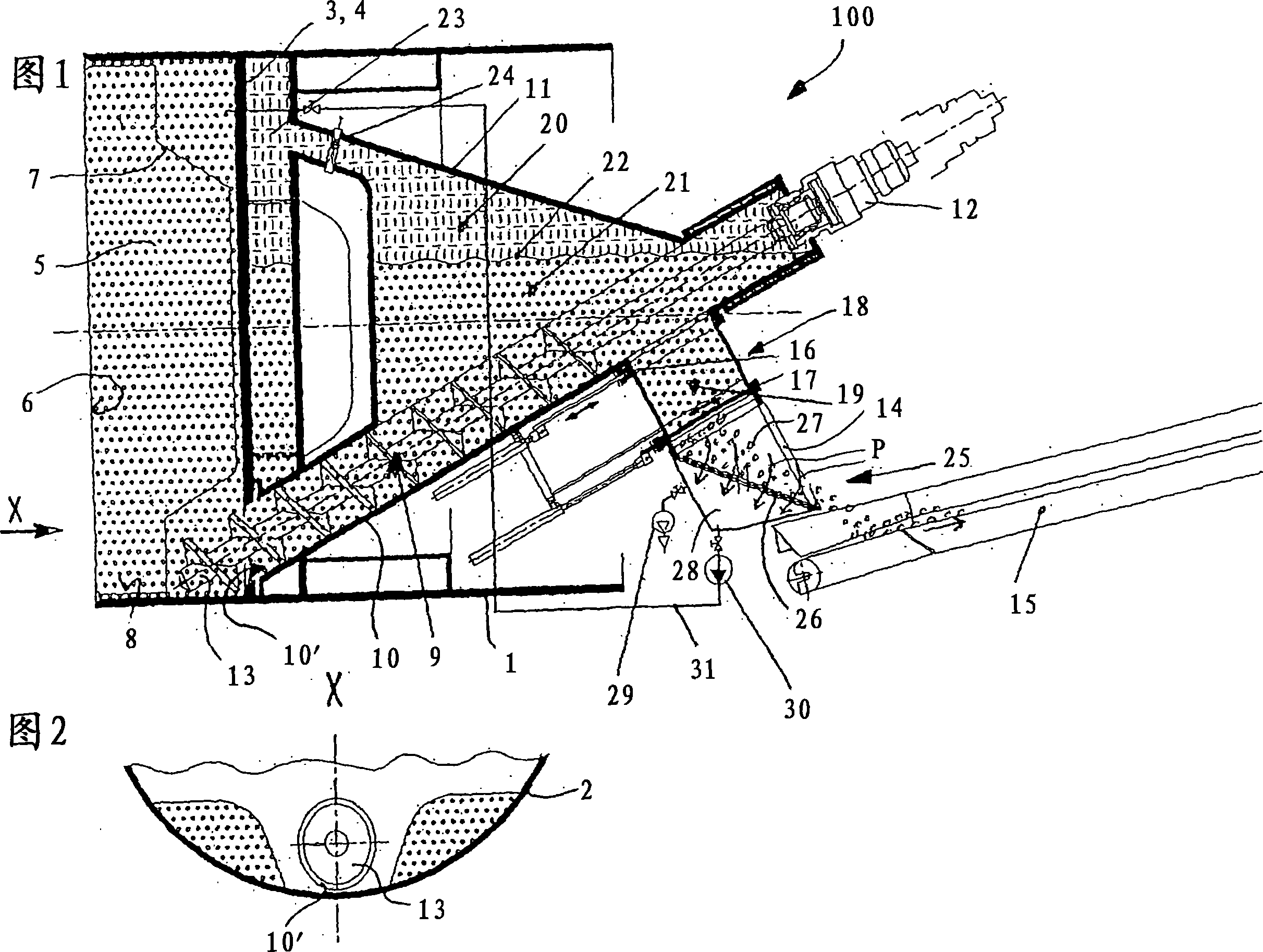
[0045] The tunnel boring machine generally indicated at 100 comprises a body 1 , its outer surface 2 and its rear wall 4 functioning as a rear wall 3 forming a drilling head space 5 behind the working face.

[0046] A drill head 7 of known design works in the drill head space. In the region of the base 8 of the drilling head space 5 a screw conveyor 9 opens into the drilling head space 5 . The screw conveyor 9 has a housing 10 which can be closed in a gas-tight manner relative to the surroundings, which in the closed state only communicates with the drilling head space 5 .

[0047] The housing 10 is initially tubular in the exit region of the drilling head space. Rising in the conveying direction. Adjoining the tubular region of the housing 10 is an upwardly extending groove-shaped extension 11 , which opens into a pressure chamber 23 arranged behind the rear wall 3 . The pressure chamber 23 can be separated from the groove-shaped extension 11 by means of a closing slide va...


PUM


Abstract

The invention relates to a method for driving a tunnel borehole. According to said method, drilled material that is detached from the breast is evacuated from a drill bit space (5) formed by the breast and the exterior faces of a machine body (1) and a rear wall (3) located at a distance from the breast with the aid of a mixture of liquid and drilled material which is fed to the drill bit space (5) as well as a conveying device whose feeding end is located within the drill bit space and whose discharge end is positioned outside said drill bit space. The mixture of liquid and drilled material is pressurized by means of an air cushion. Also the invention relates to a tunnel drilling machine or driving machine for carrying out the inventive method.

Description

technical field [0001] The invention relates to a method for boring tunnel holes and a tunnel boring machine or roadheader suitable for applying the method. Background technique [0002] If it is desired to excavate a tunnel hole with the support of a working face (Ortsbrust), the following two methods have hitherto been used: [0003] a) In order to support the working face when using the so-called mud method, the drilling head space is supported by means of a support fluid (eg bentonite) in order to prevent collapse. The removal of the drilling material takes place by means of a conveying device which communicates with the drilling head space, and a suction connection is arranged on its outlet for discharging the mixture of drilling material and bearing fluid from the pressure chamber. At another point, the drilling head space is supplied with "fresh" bearing fluid corresponding to the withdrawn bearing fluid volume, so that the desired bearing pressure on the working fac...

Claims


Application Information

Patent Timeline
IPC IPC(8): E21D9/04
CPCE21D2009/065E21D9/06E21D9/065
Inventor N·克洛伊特斯
Owner WIRTH MASCH UND BOHRGERATE FAB GMBH
Why Eureka
Eureka Blog
Learn More