
Prestressed concrete hollow pile production pile
A hollow pile and concrete technology, applied in ceramic forming machines, reinforcement forming, manufacturing tools, etc., can solve the problems of high equipment maintenance and transportation costs, high cost of pipe piles, complicated production processes, etc., and achieve the structure of production equipment. Simple, low power and simple production process
- Summary
- Abstract
- Description
- Claims
- Application Information
AI Technical Summary
Problems solved by technology
Method used
Image

Examples
Embodiment Construction
[0020] Further description will be given below in conjunction with the embodiments and accompanying drawings.
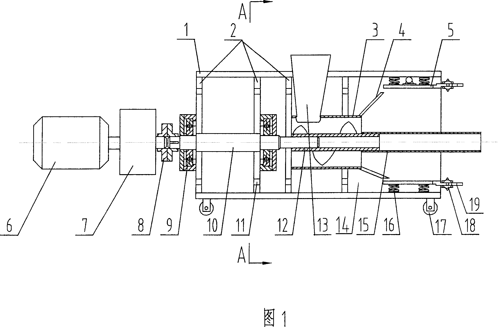
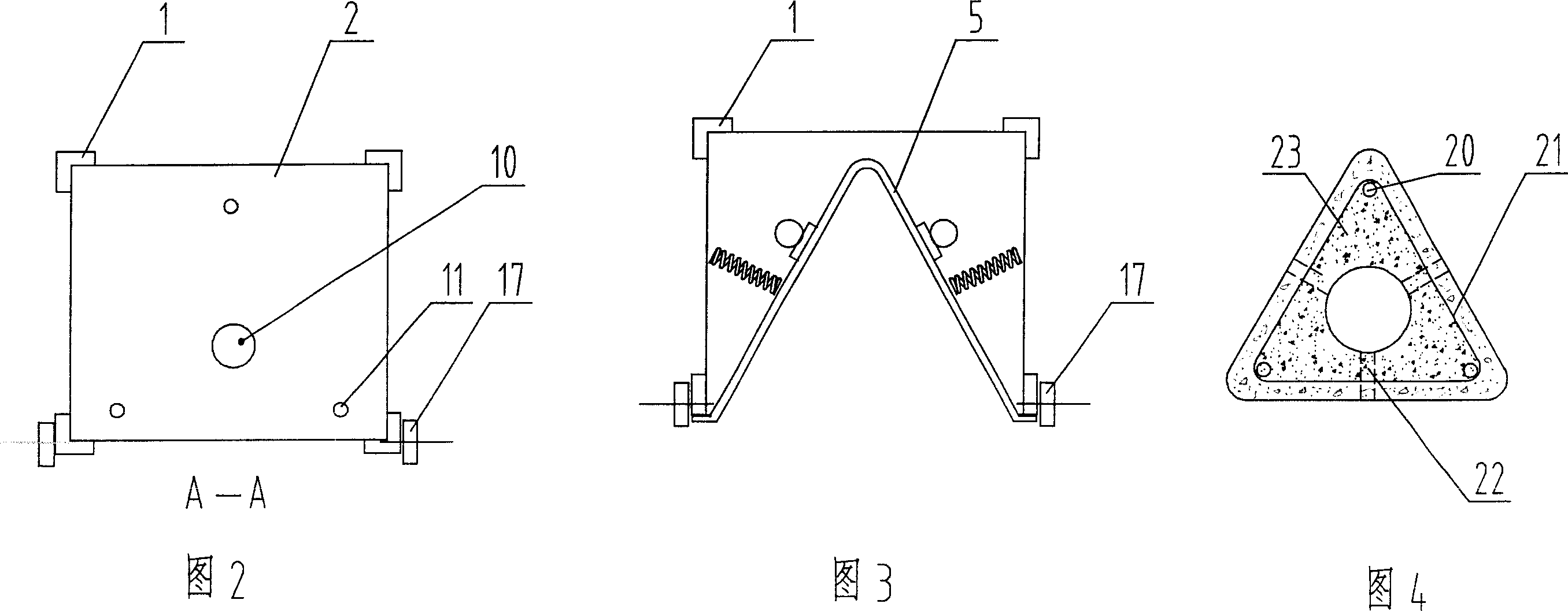
[0021] The prestressed concrete hollow pile production machine provided by the embodiment is composed of a support 1, a support plate 2, an outer tube 3, a guide plate 4, a vibration formwork 5 with a power device, a power motor 6, a gearbox 7, a shaft coupling 8, Bearing 9, power transmission shaft 10, helical pipe 12 with blade, feed opening 13, inner hole-forming pipe 15, spring 16, traveling wheel 17, rolling gear 18, hole-getting rod 19 etc. are formed.
[0022] The support plate 2 on the support 1 and the main rib through hole 11, the outer tube 3 with the feed port 13, the guide plate 4, and the vibrating mold frame 5 are the fixed parts of the body, and the four corners of the support bottom are equipped with walking wheels 17; 6 and the gearbox 7 connected to its power output shaft end, the shaft coupling 8, the transmission shaft 10, the spiral pipe 11, and...
PUM
 Abstract
Description
Claims
Application Information