Supercharge Your Innovation With Domain-Expert AI Agents!

Difluoro-methane production process

A difluoromethane and production process technology, applied in the field of refrigerants, can solve the problems that the feed state of dichloromethane and the optimal feed temperature range are not given, and the feed temperature range of hydrogen fluoride is not given, so as to reduce the reaction The corrosion phenomenon of the device, the effect of improving the utilization rate of raw materials and product yield

Active Publication Date: 2007-07-11
SHANDONG DONGYUE CHEM
View PDF6 Cites 12 Cited by
  • Summary
  • Abstract
  • Description
  • Claims
  • Application Information

AI Technical Summary

Problems solved by technology

However, the optimum feed temperature range of hydrogen fluoride is not given, nor is the feed state and optimum feed temperature range of dichloromethane

Method used


Image

  • Difluoro-methane production process

Examples


Embodiment 1

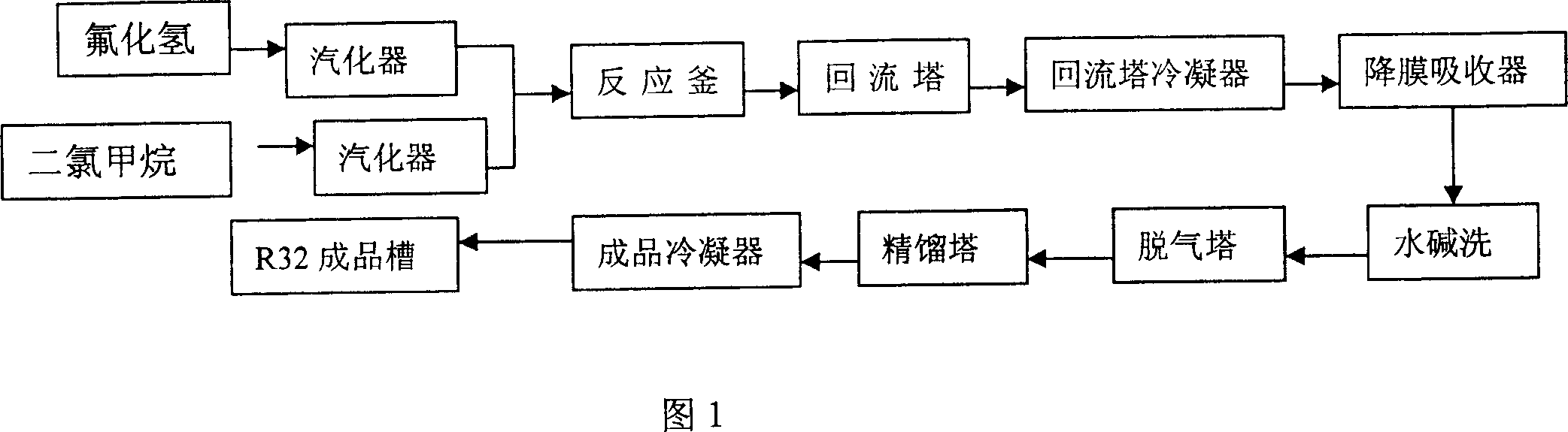
[0026] Hydrogen fluoride and dichloromethane are respectively pressed into the raw material vaporizer through a metering pump at a mass ratio of 1:2. Hydrogen fluoride vaporizes to a temperature of 100°C, and dichloromethane vaporizes to a temperature of 95°C. Then enter into the reactor equipped with fluorination catalyst to react. The reaction temperature is 95°C, and the reaction pressure is 1.2MPa. The crude difluoromethane produced by the reaction passes through the reflux tower and reflux condenser, and then the hydrogen chloride is removed by the falling film absorber, and then the pure difluoromethane is obtained after washing with water, alkali washing, degassing and rectification. After analysis, the purity of difluoromethane is ≥99.8%, and the utilization rate of raw materials is ≥95%. The reactor was not corroded during the implementation period.

Embodiment 2

[0028] Hydrogen fluoride and dichloromethane are respectively pressed into the raw material vaporizer through a metering pump at a mass ratio of 1:1.5. Hydrogen fluoride vaporizes to a temperature of 90°C, and dichloromethane vaporizes to a temperature of 95°C. Then enter into the reactor equipped with fluorination catalyst to react. The reaction temperature is 95°C, and the reaction pressure is 1.2MPa. The crude difluoromethane produced by the reaction passes through the reflux tower and reflux condenser, and then the hydrogen chloride is removed by the falling film absorber, and then the pure difluoromethane is obtained after washing with water, alkali washing, degassing and rectification. After analysis, the purity of difluoromethane is ≥99.8%, and the utilization rate of raw materials is ≥95%. The reactor was not corroded during the implementation period.

Embodiment 3

[0030] Hydrogen fluoride and dichloromethane are respectively pressed into the raw material vaporizer through a metering pump at a mass ratio of 1:2.5. Hydrogen fluoride vaporizes to a temperature of 100°C, and dichloromethane vaporizes to a temperature of 110°C. Then enter into the reactor equipped with fluorination catalyst to react. The reaction temperature is 95°C, and the reaction pressure is 1.2MPa. The crude difluoromethane produced by the reaction passes through the reflux tower and reflux condenser, and then the hydrogen chloride is removed by the falling film absorber, and then the pure difluoromethane is obtained after washing with water, alkali washing, degassing and rectification. After analysis, the purity of difluoromethane is ≥99.8%, and the utilization rate of raw materials is ≥95%. The reactor was not corroded during the implementation period.


PUM


Abstract

The invention discloses a manufacturing method of difluoromethane, which comprises the following steps: allocating raw material of hydrogen fluoride and dichloromethane with weight rate at 11. 5-3. 0; gasifying to 70-130 deg. c; injecting in the fluorination reactor with catalyst under 0.8-1. 6Mpa at 80-140 deg. c; generating rough product of difluoromethane; separating through reflux tower and reflux condenser; generating hydrogen chloride through falling-film adsorber; washing through water and alkaline; degassing; rectifying to obtain the product. The invention also provides the following equipments: two carburetors, one fluorination reactor, one set of reflux tower and reflux condenser respectively, one falling-film adsorber, washing tower, alkalin washing tower, degassing tower, rectifying tower.

Description

technical field [0001] The invention belongs to the field of refrigerants, and relates to a difluoromethane production process. Specifically, it reacts the preheated raw material dichloromethane and hydrogen fluoride in the liquid phase under the condition of the presence of a fluorination catalyst. Difluoromethane can be produced continuously and economically in a fluorination reactor. Background technique [0002] Difluoromethane (R32), an alternative refrigerant to chlorodifluoromethane used as an air-conditioning refrigerant. [0003] It is known that R32 is produced by reacting dichloromethane and hydrogen fluoride (HF) in a gas phase or a liquid phase in the presence of a catalyst. U.S. Patent No. 2749374 and U.S. Patent No. 2749375 describe making dichloromethane and hydrogen fluoride in the antimony fluoride catalyst (SbClxFy, x+y=3, y / (x+y)>0.8, Sb(v)> 5%) in the presence of a liquid phase reaction at a temperature of 110 to 175°C to obtain R32. However, in...

Claims


Application Information

Patent Timeline
Patent Type & Authority Applications(China)
IPC IPC(8): C07C17/20C07C19/08
Inventor 张希功宋淑伟马永安
Owner SHANDONG DONGYUE CHEM
Features
  • R&D
  • Intellectual Property
  • Life Sciences
  • Materials
  • Tech Scout
  • Unparalleled Data Quality
  • Higher Quality Content
  • 60% Fewer Hallucinations
Learn More