Loop type heat pipe structure

A heat pipe and loop technology, applied in the field of the connection structure between the evaporator and its tube body loop, can solve the problems of uncontrollable cleanliness and vacuum, slow production speed, affecting the heat transfer efficiency of the finished product, etc.

Inactive Publication Date: 2007-07-11
JIEFEI
View PDF0 Cites 7 Cited by
  • Summary
  • Abstract
  • Description
  • Claims
  • Application Information

AI Technical Summary

Problems solved by technology

[0003] In the evaporator of the known capillary pump suction loop (loop heat pipe), between the evaporator and the pipeline of the loop type heat pipe, the configuration structure of one side inlet and the other side outlet is adopted. When the evaporator and pipeline After being strung together in a loop, it is difficult to clean, vacuum or degas the inside of the pipeline. The cleanliness and vacuum inside the pipeline cannot be controlled, which will easily affect the heat transfer performance of the finished product.
Simultaneously, the evaporator of this invention application must be combined with two outer sleeves, and after the combination, the two outer sleeves must be sealed by adhesion or welding. The gun must also be carried out around the periphery of the two outer sleeves. At this time, it is easy to be interfered by the surrounding return pipes, which is not convenient for welding or adhesion.
[0004] In addition, when performing brazing (welding), the welding tool (torch) has to rotate 360 ​​degrees around the heat pipe, which will interfere with the heat pipe, and if a disassembled welding torch is used, the assembly and disassembly will take time, which will slow down the production speed. slower
In addition, if soldering is used, the solder will flow into the tube uncontrollably after melting, so that it will be sucked into the capillary tissue and cause blockage in the capillary tissue.

Method used


Image

  • Loop type heat pipe structure
  • Loop type heat pipe structure
  • Loop type heat pipe structure

Examples


Embodiment Construction

[0038] In order to further understand the features and technical content of the present invention, please refer to the following detailed description and drawings related to the present invention. However, the drawings are provided for reference and illustration only, and are not intended to limit the present invention.

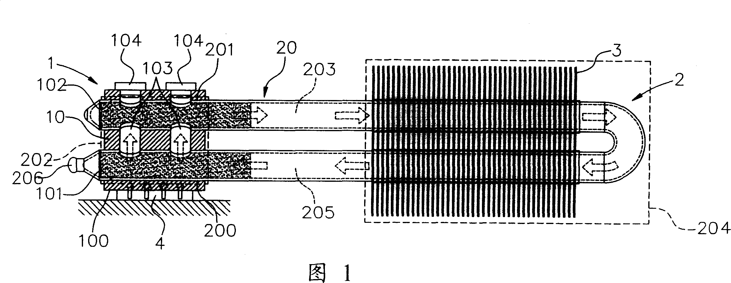
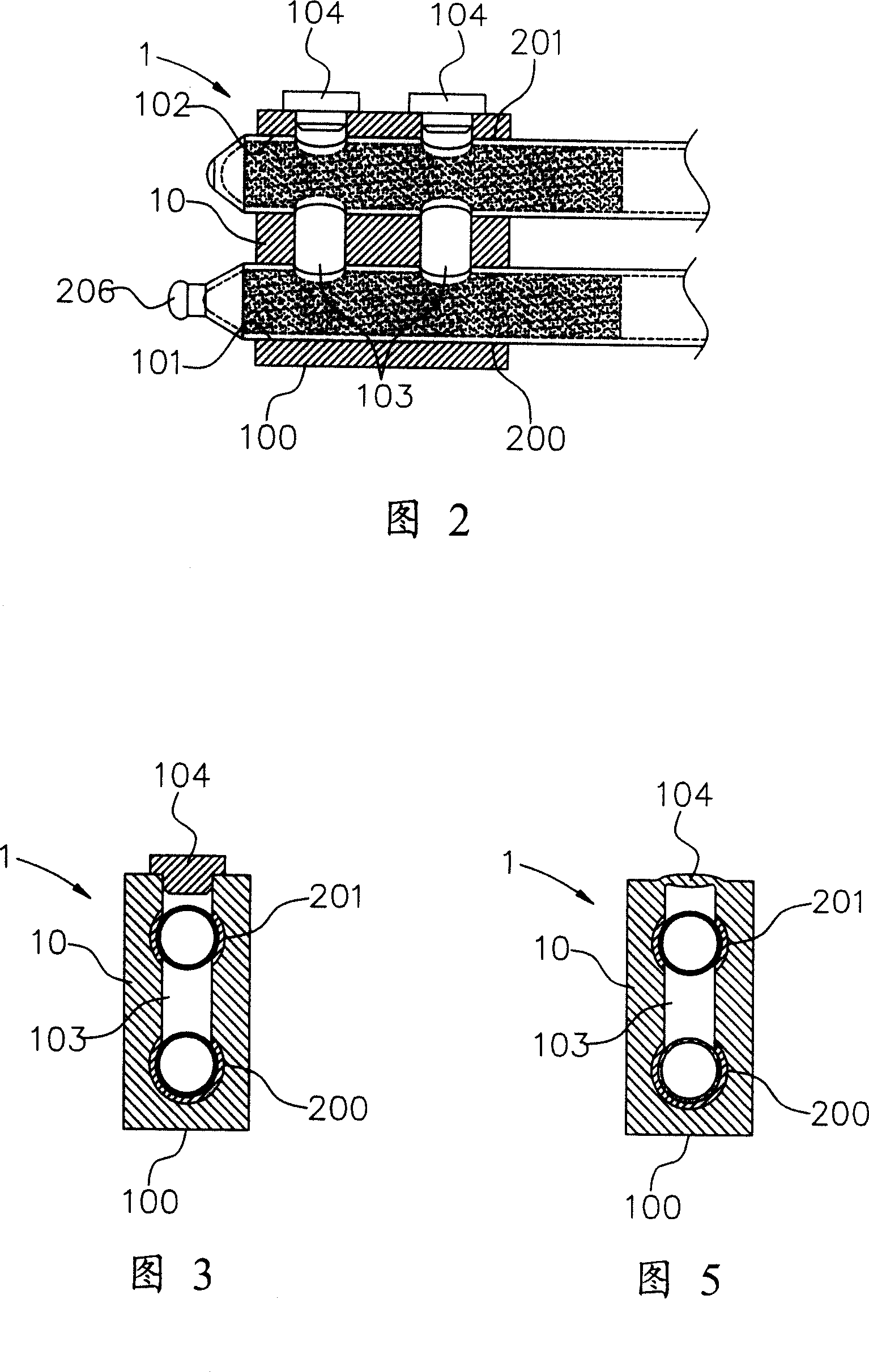
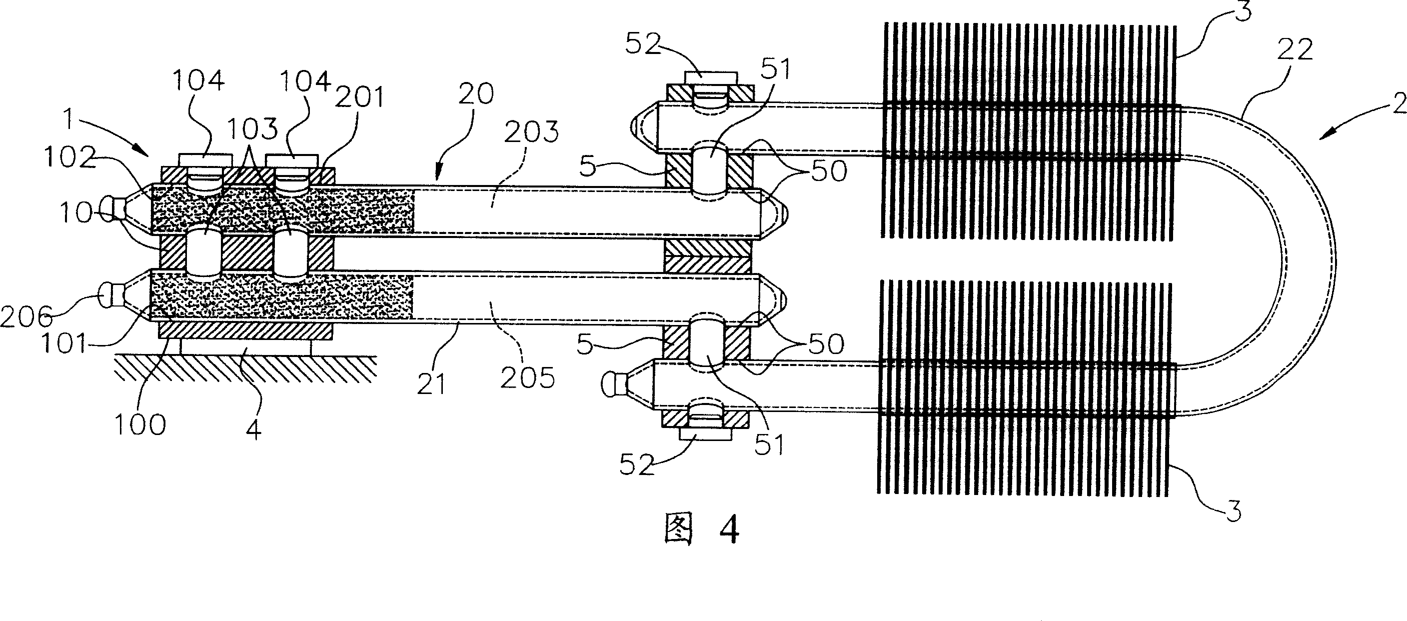
[0039] Referring to FIG. 1 , the present invention provides a loop heat pipe structure, which generally includes an evaporator 1 and a closed pipe 2 . in:

[0040] The evaporator 1 is the heat-receiving part of the loop-type heat pipe, which has an evaporation body 10 made of a heat-conducting material, such as aluminum or copper. Therefore, the evaporating body 10 is essentially a heat spreader, and has a contact surface 100 for being flat against the heat source 4 . The heat source 4 refers to electronic heating components, usually a central processing unit (CPU), but not limited thereto. In addition, at least two accommodating holes 101 , 102 ; and at le...


PUM


Abstract

The invention relates to a loop heat pipe structure, comprising evaporator and loop pipe. The evaporator comprises the evaporator body made of heat conducting material. At least two accommodating holes are set on the evaporator body and at least one channel hole through all accommodating holes are set on it. In addition, the closed pipe comprises at least two closed ends and two closed ends are fixed in two accommodating holes of evaporator. At the same time, at least one of said two accommodating holes is the penetrating hole through two sides of evaporating body and at least one end of said closed ends extrudes from the accommodating hole, which is via hole, out of the evaporator.

Description

technical field [0001] The invention relates to a loop heat pipe structure, in particular to a connection structure between an evaporator of a loop heat pipe (Loop Heat Pipe) and its pipe body loop. Background technique [0002] The loop heat pipe (Loop Heat Pipe) is a heat exchange cycle system in which the flow directions of the gas and liquid phase working fluids are all in the same direction. It is similar to the heat exchange principle in the known heat pipe (Heat Pipe), but it does not There will be no problem that the working fluid of the known heat pipe flows into each other when the liquid and gas phases change, so the heat transfer efficiency is superior to that of the known heat pipe. [0003] In the evaporator of the known capillary pump suction loop (loop heat pipe), between the evaporator and the pipeline of the loop type heat pipe, the configuration structure of one side inlet and the other side outlet is adopted. When the evaporator and pipeline After being ...

Claims


Application Information

Patent Timeline
Patent Type & Authority Applications(China)
IPC IPC(8): F28D15/02
Inventor 李嘉豪
Owner JIEFEI
Why Eureka
Try Eureka