A directly radiated media lens and its application in the micro-wave near field detection

A dielectric lens, microwave detection technology, applied in electromagnetic field characteristics, antennas, electrical components and other directions, can solve problems such as small delay, short signal propagation time, and undetectable

Inactive Publication Date: 2007-07-11
EAST CHINA NORMAL UNIV
View PDF0 Cites 6 Cited by
  • Summary
  • Abstract
  • Description
  • Claims
  • Application Information

AI Technical Summary

Problems solved by technology

If the antenna element is very close to the detection target and the signal propagation speed is fast, the signal propagation time is very short, which may cause the delay to be too small to be detected

Method used


Image

  • A directly radiated media lens and its application in the micro-wave near field detection
  • A directly radiated media lens and its application in the micro-wave near field detection
  • A directly radiated media lens and its application in the micro-wave near field detection

Examples


Embodiment Construction

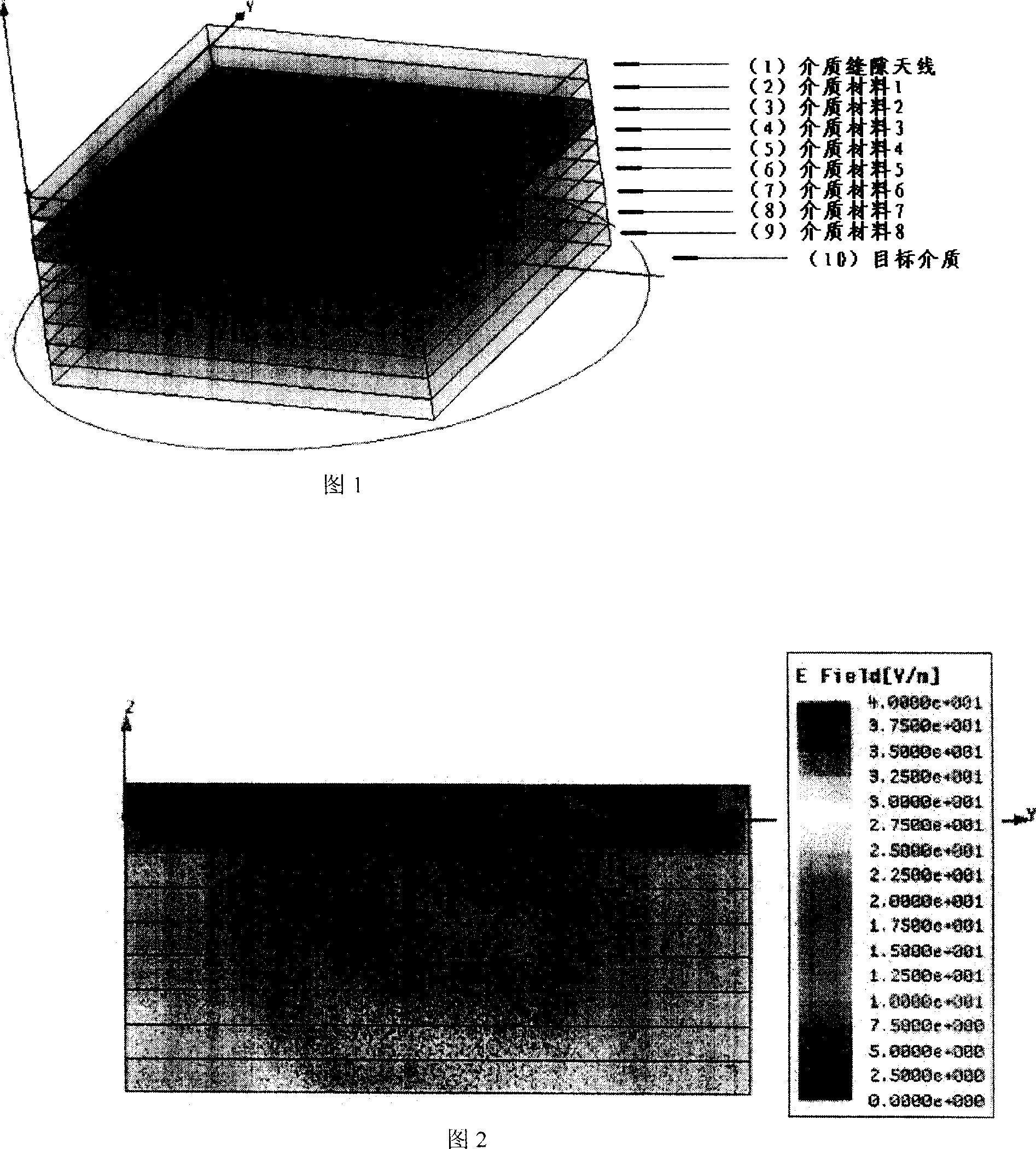
[0021] As shown in the figure, the direct-radiation dielectric lens and its application technology in microwave detection, the direct-radiation dielectric lens is composed of several dielectric sheets 1 with equidifferential transformation of the dielectric constant between the antenna and the detection target ...n overlapping composition.

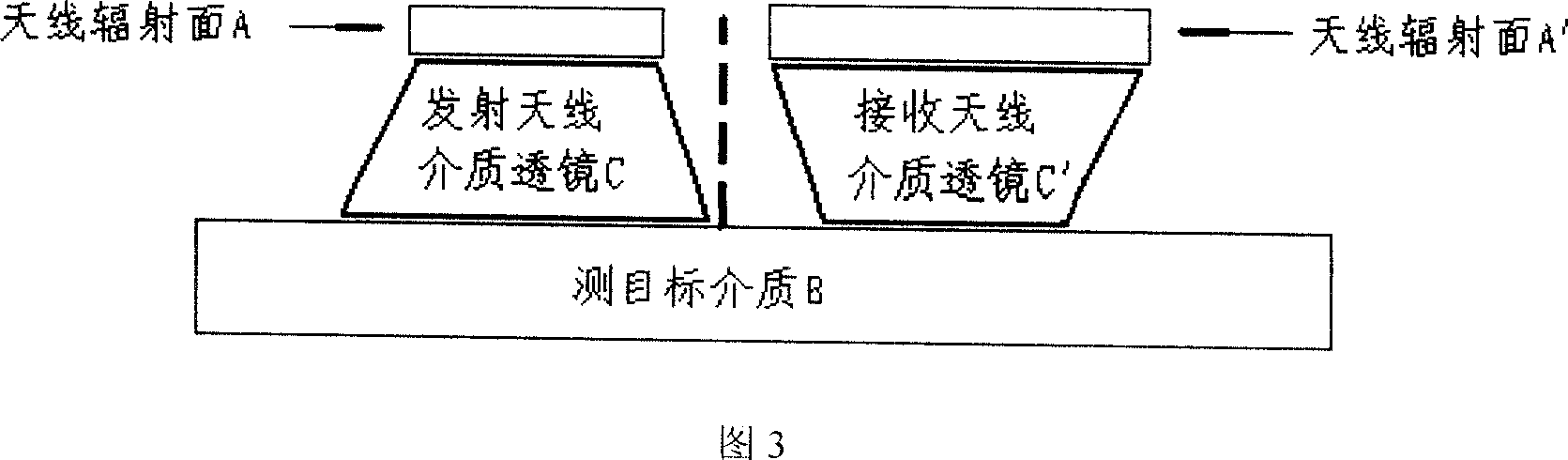
[0022] Its application method is: place two dielectric lenses C and C′ with opposite structures between the antenna radiation surface A and the detection target medium B, and each dielectric lens consists of n pieces of dielectric sheets C with equal differential changes in permittivity 1 -C n and C' 1 -C' n composition.

[0023] From the technical scheme given in accompanying drawing 1: 2 dielectric lenses with opposite structures are placed between the antenna radiation surface (assuming that the dielectric constant is 50) and the detection target medium (assuming that the dielectric constant is 36), and each dielectric lens is compos...


PUM


Abstract

This invention relates to one direct medium lens and its application in microwave detection, whose radio medium lens is composed of several dielectric parameters with equal difference change films for one to n between antenna and test objects. This invention method comprises the following steps: setting two different structure medium lens C and C'between antenna radiation surface A and test object with each lens composed of n pieces of medium slices C1-Cn and C'1-C'n with equal dielectric difference.

Description

technical field [0001] The invention relates to a microwave near-field detection technology, in particular to a direct-ray dielectric lens and its application in microwave detection. technical background [0002] In the application of near-field imaging, as well as point-to-point, point-to-multipoint wireless communication and other high-end application technologies, the system usually requires higher antenna gain. However, the gain of an antenna formed by a single antenna element is hardly higher than 20dBi. In order to improve the antenna gain, the main beam can be focused according to the principle of optical refraction: when the light passes through the optical lens, the light will converge or diverge; this principle is applied to the propagation of electromagnetic waves, and the concept of the dielectric lens is obtained: when the electromagnetic wave passes through the dielectric lens When , the main beam will be effectively focused to increase antenna gain. [0003]...

Claims


Application Information

Patent Timeline
Patent Type & Authority Applications(China)
IPC IPC(8): H01Q19/06H01Q15/02H01Q15/08G01R29/08
Inventor 姚萌
Owner EAST CHINA NORMAL UNIV
Why Eureka
Try Eureka