Resonator device and high frequency filter

a high-frequency filter and resonance device technology, applied in filters, multiple-port networks, electrical equipment, etc., can solve the problems of not being able to use one tunable filter and not being able to reverse the relationship between, and achieve the effect of a greater variety of transmission characteristics

Active Publication Date: 2018-06-26
MURATA MFG CO LTD
View PDF22 Cites 1 Cited by
  • Summary
  • Abstract
  • Description
  • Claims
  • Application Information

AI Technical Summary

Benefits of technology

[0008]In addition, with the above configuration, varying the capacitance value of the first variable capacitor enables the anti-resonant frequency closest to the resonant frequency to be inverted from the high frequency side to the low frequency side (or from the low frequency side to the high frequency side) with respect to the resonant frequency. Accordingly, when the resonator is used for, for example, a high-frequency filter, it is also possible to switch the positional relationship between the pass band and the attenuation band on the frequency axis. In addition, it is possible to adjust attenuation band characteristics or pass band characteristics in accordance with the desired transmission characteristics, thereby achieving the desired transmission characteristics.
[0012]With the above configuration, since the first inductor is an element having a small manufacturing variation, it is possible to adjust the anti-resonant frequency with high precision.
[0014]With the above configuration, the resonant frequency of the resonator is also capable of being varied and varying the capacitance of the second variable capacitor enables the resonant frequency to be adjusted to a desired resonant frequency. Accordingly, when the resonator according to the present disclosure is used for, for example, a high-frequency filter, it is possible to adjust both the attenuation band characteristics and the pass band characteristics in accordance with the desired transmission characteristics to achieve a greater variety of transmission characteristics.
[0015]According to the present disclosure, it is possible to realize the resonator device capable of adjusting the anti-resonant frequency with a simple configuration. When the resonator device is used for, for example, a high-frequency filter, it is possible to adjust the attenuation band characteristics or the pass band characteristics in order to achieve desired transmission characteristics, thereby realizing a variety of filter characteristics.

Problems solved by technology

With the tunable filter described in the Patent Document 1, it is not possible to reverse the relationship between the pass band and the attenuation band on a frequency axis even if bandpass characteristics or attenuation characteristics are capable of being adjusted.
Accordingly, it is not possible to use one tunable filter for multiple communication bands having the reverse relationship between the transmission frequency band and the reception frequency band on the frequency axis and it is necessary to provide individual tunable filters.

Method used


Image

  • Resonator device and high frequency filter
  • Resonator device and high frequency filter
  • Resonator device and high frequency filter

Examples


first embodiment

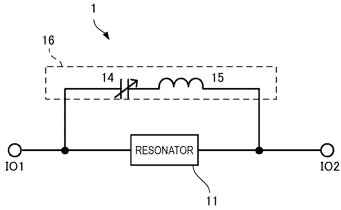
[0031]FIG. 1 is a circuit diagram of a resonant circuit 1 according to the present embodiment. The resonant circuit 1 corresponds to a resonator device according to the present disclosure.

[0032]The resonant circuit 1 includes a resonator 11. The resonator 11 is an element having a resonance point (resonant frequency) and an anti-resonance point (anti-resonant frequency). Specifically, the resonator 11 is a piezoelectric resonator and, for example, is a surface acoustic wave (SAW) device. The resonant circuit 1 according to the present embodiment has a center frequency of 800 MHz and a characteristic impedance of 50Ω. The SAW device has a structure in which a comb-shaped pattern is formed of a thin film made of Al or an Al alloy. The comb-shaped pattern is formed on a piezoelectric thin film and extracts an electrical signal within a certain frequency band. The resonator 11 may be a bulk acoustic wave (BAW) device.

[0033]The resonant circuit 1 includes a series circuit 16 in which a v...

second embodiment

[0051]A resonant circuit according to a second embodiment will now be described. The resonant circuit according to the second embodiment differs from that in the first embodiment in that both the resonance point and the anti-resonance point are capable of being adjusted.

[0052]FIG. 6 is a circuit diagram of the resonant circuit according to the second embodiment. A resonant circuit 2 has a configuration in which a series circuit 19 composed of a variable capacitor 17 and an inductor 18, which are connected in series to each other, is further connected to the resonant circuit 1A according to the first embodiment. The connection of the variable capacitor 17 and the inductor 18 in series to the resonator 11 enables the resonance point of the resonator 11 to be adjusted.

[0053]FIG. 7 is a graph illustrating impedance characteristics of the circuit in which the variable capacitor 17 and the inductor 18 are connected in series to the resonator 11. The impedance characteristics in FIG. 7 are...

third embodiment

[0060]FIG. 11 is a circuit diagram of a high-frequency filter according to a third embodiment. A high-frequency filter 3 according to the present embodiment includes a resonant circuit 30 connected to a signal line between the input-output terminals IO1 and IO2 and a resonant circuit 40 one end of which is connected to the signal line and the other end of which is grounded. The resonant circuits 30 and 40 each has the same configuration as that of the resonant circuit 2 according to the second embodiment. Specifically, an inductor 33 (43) is connected in parallel to a resonator 31 (41). An inductor 32 (42), a variable capacitor 36 (46), and an inductor 37 (47) are connected in series to the resonator 31 (41). A variable capacitor 34 (44) and an inductor 35 (45), which are connected in series to each other, are connected in parallel to the resonator 31 (41) and the inductor 32 (42), which are connected in series to each other.

[0061]In the high-frequency filter 3, the resonant circuit...


PUM


Abstract

A resonant circuit includes a resonator having a resonant frequency and an anti-resonant frequency, an inductor connected in series to the resonator, an inductor connected in parallel to the resonator, and a series circuit in which a variable capacitor is connected in series to an inductor (15). The series circuit is connected in parallel to the resonator. The anti-resonant frequency closest to the resonant frequency of the resonator is moved toward higher frequencies or lower frequencies of the resonant frequency on a frequency axis with a variation in the capacitance value of the variable capacitor. With this configuration, a resonator device and a high-frequency filter are provided, in which the relationship between a transmission frequency band and a reception frequency band on the frequency axis is applicable to a variety of multiple communication bands.

Description

BACKGROUNDTechnical Field[0001]The present disclosure relates to a resonator device having a resonance point and an anti-resonance point and to a high-frequency filter including the resonator device.[0002]Communication apparatuses in recent years establish communication in various frequency bands. Accordingly, the communication apparatuses each include multiple filters corresponding to the multiple frequency bands and switch the filter to be used for every required frequency band. The filter is desirably a tunable filter (variable filter) capable of varying bandpass characteristics across wider frequency bands, for example, as described in Patent Document 1.[0003]Patent Document 1: Japanese Unexamined Patent Application Publication No. 2009-130831BRIEF SUMMARY[0004]The communication apparatuses in recent years have transmission frequency bands at the low frequency side or the high frequency side of reception frequency bands, depending on their communication bands. With the tunable f...

Claims


Application Information

Patent Timeline
Patent Type & Authority Patents(United States)
IPC IPC(8): H03H9/54H03H5/12H03H7/01H03H9/64H03H9/52H03H9/56H03H9/02
CPCH03H9/542H03H5/12H03H7/0115H03H7/0161H03H9/54H03H9/545H03H9/64H03H9/6403H03H9/6423H03H9/6483H03H9/568H03H2210/025H03H2009/02204
Inventor KANDO, HAJIMETANI, MASAKAZU
Owner MURATA MFG CO LTD
Why Eureka
Try Eureka