
Packaging shell and a power module having the same

a power module and packaging shell technology, applied in the direction of electrical apparatus casings/cabinets/drawers, electrical apparatus casings/cabinets/drawers, etc., can solve problems such as cracks

Active Publication Date: 2018-07-03
DELTA ELECTRONICS (SHANGHAI) CO LTD
View PDF14 Cites 0 Cited by
  • Summary
  • Abstract
  • Description
  • Claims
  • Application Information

AI Technical Summary

Benefits of technology

The solution effectively prevents substrate rupture by distributing compressional forces and enhancing the reliability of the packaging assembly, ensuring efficient heat dissipation and improved module performance.

Problems solved by technology

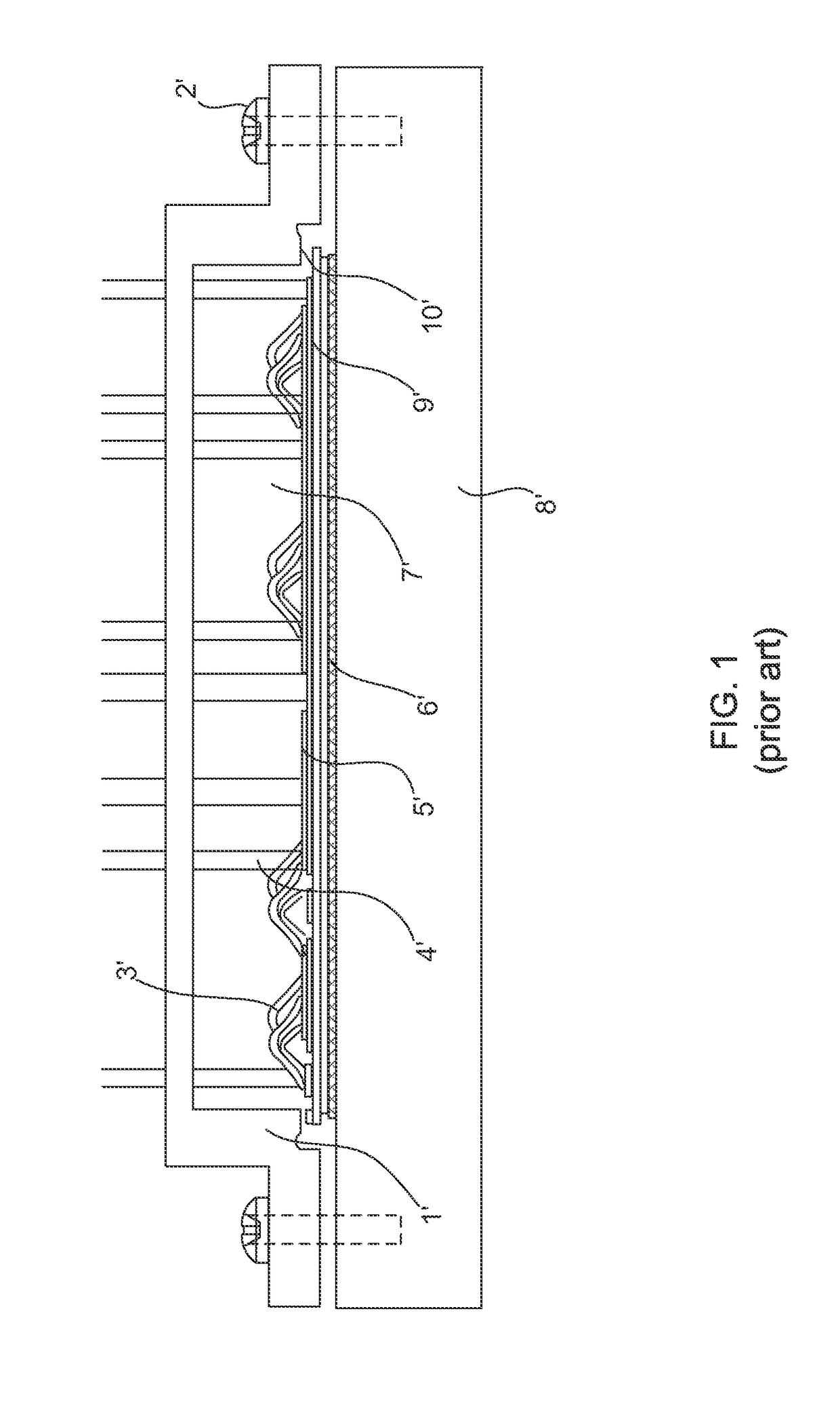
However, for the fragile substrate 9′, such as DCB (Direct Copper Bonded), a crack may happen when the shell 1′ is installed by screwing and locking because the fragile substrate 9′ cannot afford the stress applied thereof.

Method used


Image

  • Packaging shell and a power module having the same
  • Packaging shell and a power module having the same
  • Packaging shell and a power module having the same

Examples


Embodiment Construction

[0054]Among those benefits and improvements have been disclosed, other objects and advantages of this invention will become apparent from the following description taken in conjunction with the accompanying figures. Detail embodiments of the present invention are disclosed herein; however, it is to be understood that the disclosed embodiments are merely illustrative of the invention that may be embodied in various forms. In addition, each of the examples given in connection with the various embodiments of the invention is intended to be illustrative, and not restrictive.

[0055]Throughout the specification and claims, the following terms take the meanings explicitly associated herein, unless the context clearly dictates otherwise. The phrases “In some embodiments” and “in some embodiments” as used herein do not necessarily refer to the same embodiment(s), though it may. Furthermore, the phrases “in another embodiment” and “in some other embodiments” as used herein do not necessarily r...


PUM


Abstract

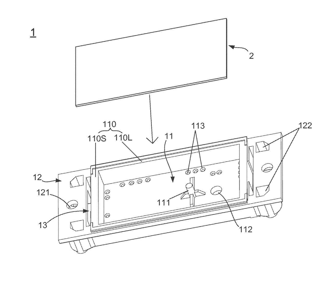
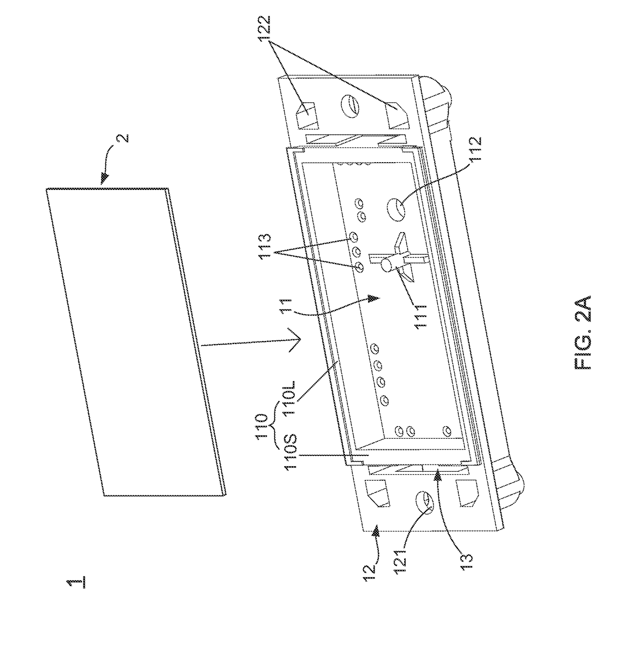
The present invention provides a packaging shell and a power module having the same. The packaging shell mainly comprises an accommodating recess for receiving a substrate disposed with a plurality of electronic devices / components, so as to make the substrate be further assembled with a heat sink through the support of the packaging shell. Most importantly, in the present invention, the accommodating recess has a stepped surface for contacting with the substrate, and the stepped surface is a curve surface having a flatness difference. By such design, the compressional force generated when assembling the packaging shell, the heat sink and the system circuit board can be uniformly transmitted to substrate via the curve surface structure; such that the compressional force is avoid from being concentrated to a certain point on the substrate, and then the substrate is protected from being ruptured due to the action of the concentrated compressional force.

Description

BACKGROUND OF THE INVENTION[0001]1. Field of the Invention[0002]The present invention relates to a plastic packaging structure, and more particularly, to a packaging shell and a power module having the same.[0003]2. Description of the Prior Art[0004]High power efficiency and high power density are industrial basic demands on power converters; wherein, high power efficiency implies energy conservation, carbon reduction, environment protection, and low operation cost, and high power density means small volume, light weight, low transportation cost, less space occupation, and low built cost.[0005]Therefore, improving the space utilization inside the power converter is one of key factors to make the power converter achieve high power density and high power efficiency. Besides, semiconductor device is also an important factor for improving the space utilization inside the power converter, and the commonly used way is to dispose a plurality of semiconductor devices on a packaging shell fo...

Claims


Application Information

Patent Timeline
Patent Type & Authority Patents(United States)
IPC IPC(8): H05K1/02H05K5/02H05K5/06H01L23/04H01L23/00H01L23/10H05K7/14H01L23/373
CPCH01L23/04H01L23/562H05K7/1432H01L23/10H01L23/3735H01L2224/48091H01L2224/48227H05K7/1417H05K1/0203H05K5/069H05K7/142H01L2924/00014H01L2224/73265H01L2224/48137H01L2224/32225H05K7/14329
Inventor WANG, XIANMINGHONG, SHOUYU
Owner DELTA ELECTRONICS (SHANGHAI) CO LTD
Learn More