Composting system and method

a technology of composting system and composting method, which is applied in the field of composting system and method, can solve the problems of easy transportation and small volume of components, and achieve the effects of promoting the growth of aerobic bacteria, and reducing the density of air

Active Publication Date: 2018-07-17
HULLS JOHN
View PDF12 Cites 0 Cited by
  • Summary
  • Abstract
  • Description
  • Claims
  • Application Information

AI Technical Summary

Benefits of technology

[0015]This disclosure provides, among other things, a system useful for composting, in particular, for composting material such as feces that may comprise pathogenic material. In one embodiment, the system includes a container configured to contain a composition and comprising (i) insulation, (ii) an air intake and (iii) a vent. A composition is provided to the container, which composition comprises (i) aerobic microorganisms, (ii) a carbon source and (iii) a nutrient source (such as feces) sufficient to support growth of the aerobic microorganisms in an aerobic environment. Prior to mixing, the waterborne waste / feces mixture may be in an anaerobic state. Mixing the composition prior to adding the mixture to the container adds oxygen, and creates passages for air flow, thus promoting the growth of aerobic bacteria which are present, and rapidly eliminates the odors from the anaerobic bacteria. An aerobic environment is maintained in the composition by providing air through a convection current referred to as a “stack effect” that moves air into the air intake, and out the vent in such a way to distribute air to the base of the composition and thus to the aerobic microorganisms. The configuration of the container is such that the flow path of the heated air is generally vertical. The vertical flow of the air current is maintained by heating the air in the composition with heat generated by aerobic microorganisms through aerobic respiration, and contained in the container through insulation provided, for example, by walls of the container. This lowers the density of the air in the composting material above the air intake and causing flow from the increased pressure of the more dense air beneath the material, thus creating what is called a “stack effect”. The stack effect uses the heat convection from the composting material to create a draft akin to that of a fireplace drawing air up a chimney, with the heat of the respiring microbial mass representing the fire. The fireplace analogy also applies inasmuch that it is necessary to provide an even inflow of oxygen to support the combustion process or heat generating respiration of the composting bacteria. This provides air more effectively to material in the pile than purely random lateral diffusion of gasses from slots in a base beneath the composting material. The air flow is self-sustaining as the aerobic microorganisms generate heat to maintain the convention current, and the convection current provides air to the aerobic microorganisms with which the microorganisms can respire and grow. Under such conditions, the microbial population rapidly and uniformly changes to mostly thermophilic bacteria, capable of producing sufficient heat to inactivate normal gut bacteria (e.g., the gut microbiome), and many other harmful biological forms. The use of specialized geotextile drainage fabric for the aeration distribution, coupled with straw bales for walls and / or gabion cell construction mean that thermopile cells can be constructed on a simple graded surface with minimal capital expense, and essentially considered a consumable part of the process. In addition, the components are of very small volume and easily shipped and stored for military and disaster relief applications.

Problems solved by technology

In addition, the components are of very small volume and easily shipped and stored for military and disaster relief applications.

Method used


Image

  • Composting system and method
  • Composting system and method
  • Composting system and method

Examples


examples

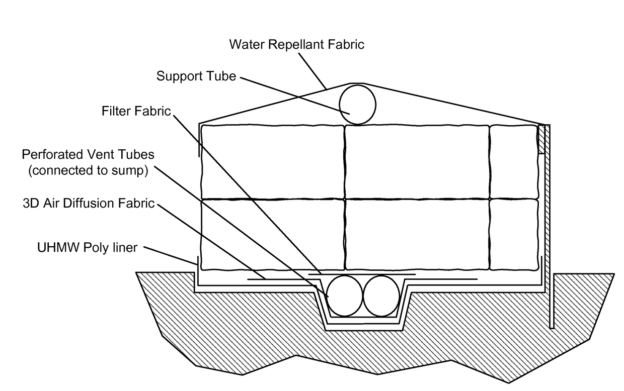
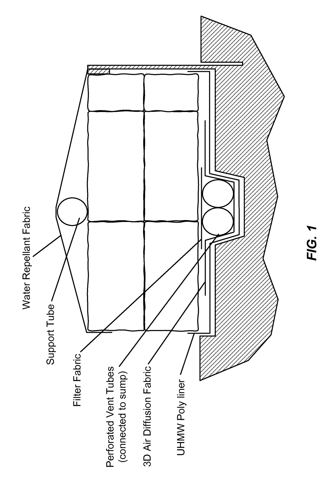
[0099]Waste Collection

[0100]Sanitary waste can be collected from 20 housing units equipped with ULF toilets every 2 weeks. Minimal handling is then required for compost pile construction. The sanitary waste is mixed with a defined amount of greenwaste (food waste, wood chips, sawdust, straw) using a modified, agricultural vertical feed mixer. This improves moisture content and aerobic structure. The mixer includes scales to measure the correct ratios of components and its output conveyor allows placement of the mixed material directly into the composting cell, thus eliminating handling and minimizing operator exposure to the waste. The pile is then continuously monitored for temperature, oxygen and moisture, and periodically sampled for microbial community and pathogen analysis. Thermophilic temperatures are typically achieved within the first 3-4 days and persist for at least one month before removal of finished compost material that is certified pathogen-free. This complies with e...


PUM

PropertyMeasurementUnit
volumeaaaaaaaaaa
temperatureaaaaaaaaaa
densityaaaaaaaaaa

Abstract

This disclosure provides a composting system and method. The system comprises: (a) a container configured to contain a composition and comprising (i) insulated walls, (ii) an air intake and (iii) a vent; and (b) a composition contained in the container. The composition comprises aerobic microorganisms, a carbon source and a nutrient source sufficient to support growth of the aerobic microorganisms. The container is sufficiently insulated so that heat generated by aerobic respiration is sufficiently retained in the container to maintain a heat gradient in the container. The container is dimensioned to generate a stack effect that moves air into the air intake, through the composition and out the vent. The moving air provides oxygen to support growth of aerobic microorganisms, making the stack effect self-sustaining as long as a carbon source and nutrients last. The insulation can maintain temperatures in the composting cell sufficient to kill pathogenic microorganisms.

Description

CROSS-REFERENCE TO RELATED APPLICATIONS[0001]This application is a National Stage entry of PCT / US2014 / 038007, filed May 14, 2014, which claims the benefit of the filing date of United States provisional patent application 61 / 823,857, filed May 15, 2013.STATEMENT AS TO FEDERALLY SPONSORED RESEARCH[0002]None.BACKGROUND OF THE INVENTION[0003]In composting, microorganisms decompose organic matter into compost. This compost can be useful as fertilizer. Materials necessary for composting include a carbon source, a nutrient source (in particular a nitrogen source), water and oxygen. When materials are combined, aerobic microorganisms metabolize the organic material to produce compost. This metabolism also generates heat. Sometimes this can be seen as steam rising from a compost pile.[0004]Oxygen must be available to an aerobic composting system for use by aerobic microorganisms. In dynamic composting systems, the compostable materials are periodically turned to expose them to fresh air. In...

Claims


Application Information

Patent Timeline
Patent Type & Authority Patents(United States)
IPC IPC(8): C05F17/02C05F3/04C05F3/06C05F17/00C05F3/00
CPCC05F17/0258C05F3/00C05F3/04C05F3/06C05F17/00C05F17/02C05F17/0036Y02W30/47Y02E50/343Y02P20/145Y02W30/43C05F17/90C05F17/964C05F17/20Y02A40/20Y02E50/30Y02W30/40C12P1/04C12P5/00C12P1/00
Inventor HULLS, JOHN
Owner HULLS JOHN
Why Eureka
Try Eureka