Inductive power transfer control using energy injection

a technology of inductive power transfer and energy injection, which is applied in the direction of electric variable regulation, process and machine control, instruments, etc., can solve the problems of unpredicted voltage and current overshoot during load transients, complicated controller design for these power supplies, and high cos

Active Publication Date: 2018-08-21
AUCKLAND UNISERVICES LTD
View PDF9 Cites 0 Cited by
  • Summary
  • Abstract
  • Description
  • Claims
  • Application Information

AI Technical Summary

Benefits of technology

[0005]It is an object of the present invention to provide an improved IPT system control method or apparatus, or to provide an approved IPT system power supply, or to provide an improved IPT system which at least ameliorates one or more of the disadvantages of known systems, or at least provides a useful alternative.
[0024]In use, the IPT primary power supply will be located in proximity with an IPT secondary pick-up circuit for transferring power to a connected load. Such an arrangement allows for easily adapting to changes in the coupling conditions, such as distance between coils, as well as loading conditions on the secondary. A shorter duration pattern allows for adapting rapidly to such transients, whilst a longer duration patterns allows for finer control of the power transfer in order to more closely align with the set-point and increases efficiency. In particular losses and heating can be reduced. The flexibility of control provided by various duration patterns also allows for supporting greater coupling gaps. In addition, by increasing efficiency and more flexible management of the system, the stresses on circuit components such as switches and capacitors are reduced, thereby either extending their effective life, or allowing component de-rating and hence cheaper provision. The greater flexibility provided also enables system designs in which switching components in the secondary can be reduced, thereby extending secondary life and reliability. This may be particularly important in applications such as implantable medical devices.
[0026]In an embodiment the distribution of energy injection events in a series of patterns is changed, whilst maintaining the same number of energy injection events in each pattern in the series. By maintaining the same number of injection events but varying the pattern, the power transferred is constant and a communication channel is created by the ability to detect the pattern series. This can be used to send digital information. The modulation of the power transferred may alternatively be used to vary and / or reduce the electromagnetic noise generated by the power system. This may be particularly advantageous when deployed in sensitive environments.
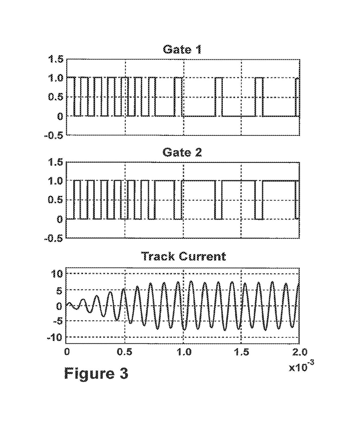
[0028]Embodiments may provide for a number of switching patterns having different numbers of cycles in order to handle different conditions. Selecting or switching between these patterns may be directly dependent on changes in the parameter value, or selecting a new pattern may depend on the variation in the parameter value over time. Thus for example, as the system appears to stabilise after a transient condition, longer and longer duration patterns may be selected.
[0043]In an embodiment, the control signal is arranged to modulate the selection of switching patterns in response to a communications signal in order to transmit a message to the secondary. Alternatively or additionally, the change in switching patterns may be controlled in order to reduce or change electromagnetic noise.
[0046]By utilising this arrangement on both the primary and secondary sides, duplex communications is possible, and may be used for transferring information to connected devices to control the primary and secondary themselves, for example by adjusting the resonant frequency in response to changing coupling or load conditions.

Problems solved by technology

This makes the controller design for these power supplies complicated and costly.
In practice, controlling the power available to a pick up 4 can be problematic, and in existing systems attempts to provide adequate control can result in unpredicted voltage and current overshoots during load transients or start up situations.
These can damage the switching devices or other components in the system.

Method used


Image

  • Inductive power transfer control using energy injection
  • Inductive power transfer control using energy injection
  • Inductive power transfer control using energy injection

Examples


Embodiment Construction

[0062]The invention proposes a new form of control for IPT systems, or IPT primary power supplies, in which discrete energy injection is used to control the primary power controller and thus control the IPT system as required. In particular, energy injection according to the present invention allows the power available to one or more pick ups to be controlled, as will be described further below.

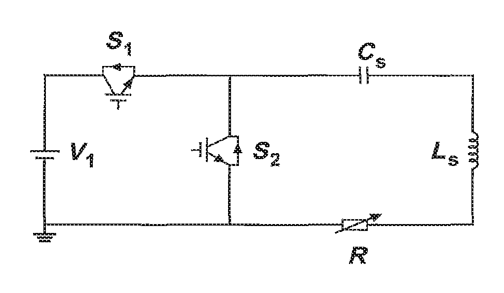
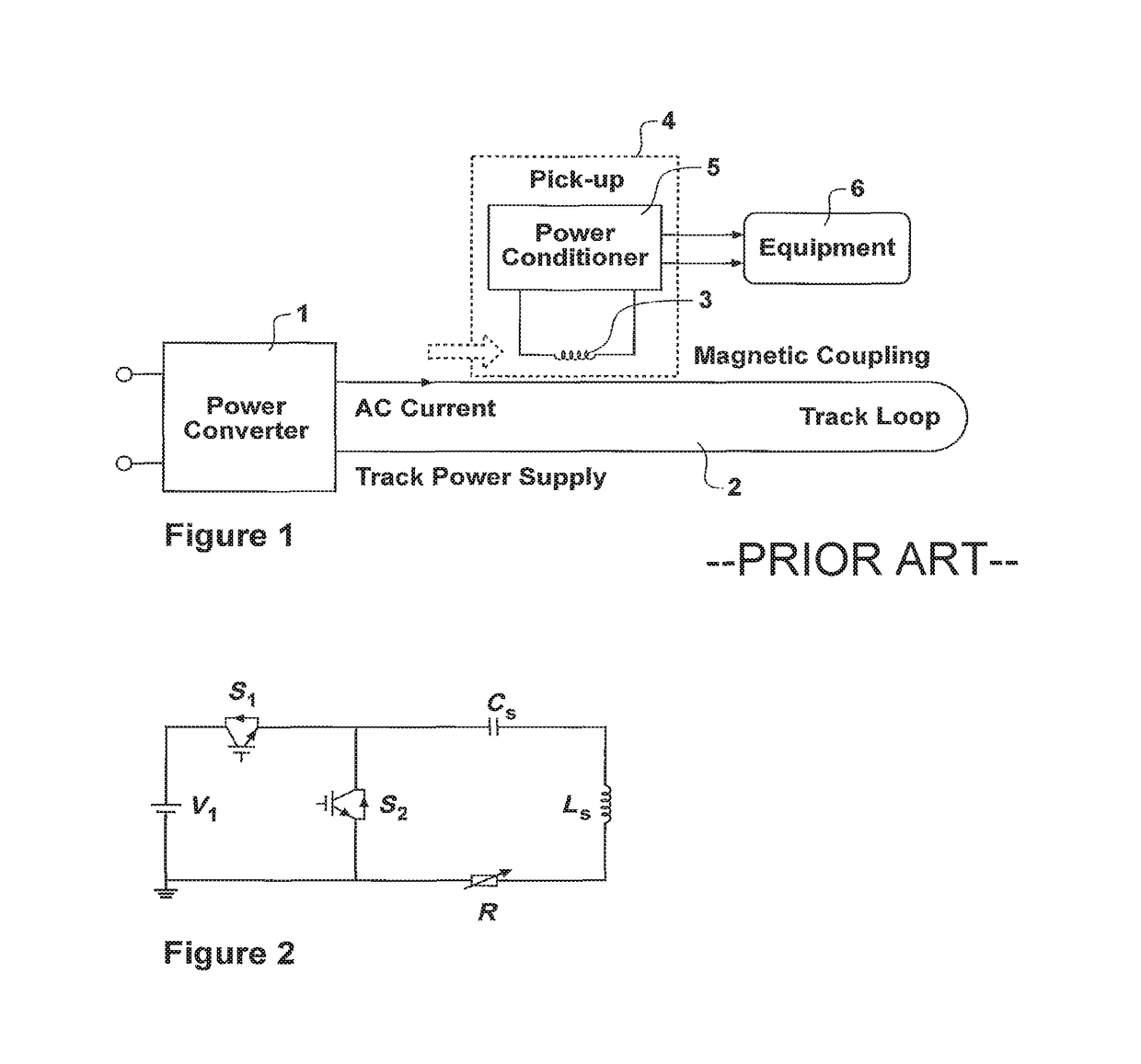
[0063]Referring to FIG. 2, one example of a power converter for use according to the present invention is shown. Switches S1 and S2 are connected as shown with a resonant circuit comprising inductance LS and capacitance C. In practice, inductance LS comprises the track 2 as described with reference to FIG. 1, and capacitance CS is selected to tune the track at a desired resonant frequency. Load resistor R represents a variable load. As will be appreciated by a person skilled in the art the switches S1 and S2 may be operated to allow the resonant circuit to resonant.

[0064]For example, when swi...


PUM

PropertyMeasurementUnit
resonant frequencyaaaaaaaaaa
poweraaaaaaaaaa
energyaaaaaaaaaa

Abstract

The invention relates to inductive power transfer (IPT) systems, and has particular relevance to control of IPT systems, and to operation of IPT system primary power supplier. There is provided a method for controlling an IPT system primary power supply having a switched resonant circuit; the method comprising: determining the value of a parameter of the system; determining an energy injection switching pattern having a duration dependent on the parameter value; controlling the resonant circuit according to the determined energy injection switching pattern.

Description

PRIORITY CLAIM TO RELATED APPLICATIONS[0001]This application is a U.S. national stage application filed under 35 U.S.C. § 371 from International Application Serial No. PCT / NZ2013 / 000184, which was filed Oct. 1, 2013, and published as WO 2014 / 054953 on Apr. 10, 2014, and which claims priority to New Zealand Application No. 602767, filed Oct. 1, 2012, and to New Zealand Application No. 602903, filed Oct. 9, 2012, which applications and publication are incorporated by reference as if reproduced herein and made a part hereof in their entirety, and the benefit of priority of each of which is claimed herein.FIELD OF THE INVENTION[0002]This invention relates to inductive power transfer (IPT) systems, and has particular relevance to control of IPT systems, and to operation of IPT system primary power supplies.BACKGROUND[0003]Inductive power transfer (IPT) systems are well known. An example of a typical IPT system is shown in FIG. 1 in which a power supply 1 which is typically provided in th...

Claims


Application Information

Patent Timeline
Patent Type & Authority Patents(United States)
IPC IPC(8): H02J7/00H02J50/40H02J7/14H02J50/12H02J50/80H02J50/90H02J5/00H01F38/14H02J7/02H02M3/158H02J50/10H02M3/337H02M1/00
CPCH02J50/12H01F38/14H02J5/005H02J7/025H02J50/10H02J50/40H02J50/90H02M3/158H02M3/3376H02J50/80Y02B70/1491H02M2001/0058Y02B70/1433H02J7/00712Y02B70/10H02M1/0058
Inventor BUDGETT, DAVID MORTIMERHU, AIGUOLEUNG, HO YAN ALEXMCCORMICK, JOHN DANIEL
Owner AUCKLAND UNISERVICES LTD
Why Eureka
Try Eureka