Wall for a hot gas channel in a gas turbine

a gas turbine and hot gas technology, applied in the field of gas turbines, can solve the problems of reducing the life of the gas turbine, reducing affecting the service life of the turbine, so as to reduce the impact of damage, reduce the size of the hole, and restrict cracks

Active Publication Date: 2018-10-02
ANSALDO ENERGIA SWITZERLAND AG
View PDF19 Cites 5 Cited by
  • Summary
  • Abstract
  • Description
  • Claims
  • Application Information

AI Technical Summary

Benefits of technology

[0006]These two different options, firstly delineating an array of cells, and secondly delineating compartments, both solve a number of similar problems and provide a number of similar advantages. Providing cells limits the impact of damage to the hot gas surface by restricting cracks and limiting hole size. Compartments also limit the impact of damage to the hot gas surface, again by keeping the impact local. Both these options can therefore improve part lifetime.
[0007]Part lifetime is improved due to increased ease of assessment on defect allowances (i.e. how many defects can be tolerated) and whether parts can continue to be used or need replacing or repairing. The number of defects that can be allowed can also be increased. Tolerance to damage (cracks, openings, holes) in the hot gas surface is increased. Wall disintegration during emergency lifetime period can be better controlled and can be localised and slowed down.
[0008]Providing ribs and / or compartments also improves wall strength. Ribs in particular can improve heat transfer, and therefore cooling. Compartments in particular can contain cooling disruption created by cracks or holes, so that cooling effectiveness is only reduced locally. Ribs in particular can restrict crack and / or hole growth.
[0009]Preferably, separate impingement cooling holes are provided for each of the cells. This can allow for uniform cooling.
[0011]In another embodiment, the wall additionally comprises a second wall attached to and substantially perpendicular to the wall. This can improve wall strength.
[0013]In another embodiment, the back side of the wall, the pins and the ribs are integrally cast. This can improve part lifetime and stability.

Problems solved by technology

Various parts in gas turbines are subject to high temperatures, and as a result are liable to degrade or disintegrate.
However, lifetime is still limited, and once failure starts to occur (for example a crack), then the part must soon be replaced, as the damage is liable to rapidly spread.
This is particularly the case once any crack becomes big enough that significant cooling air is lost through the hole, reducing cooling effectiveness.

Method used


Image

  • Wall for a hot gas channel in a gas turbine
  • Wall for a hot gas channel in a gas turbine
  • Wall for a hot gas channel in a gas turbine

Examples


Embodiment Construction

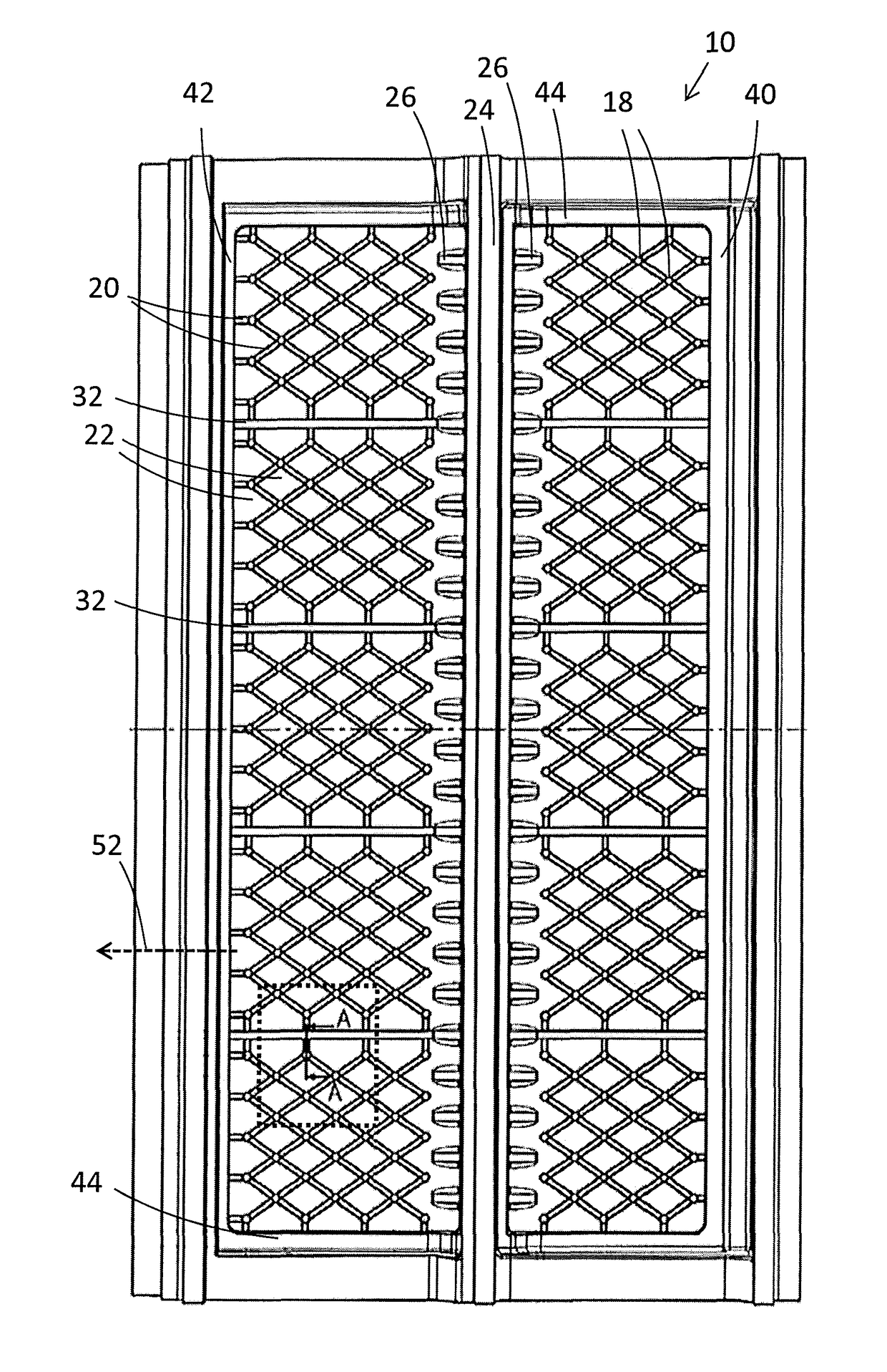
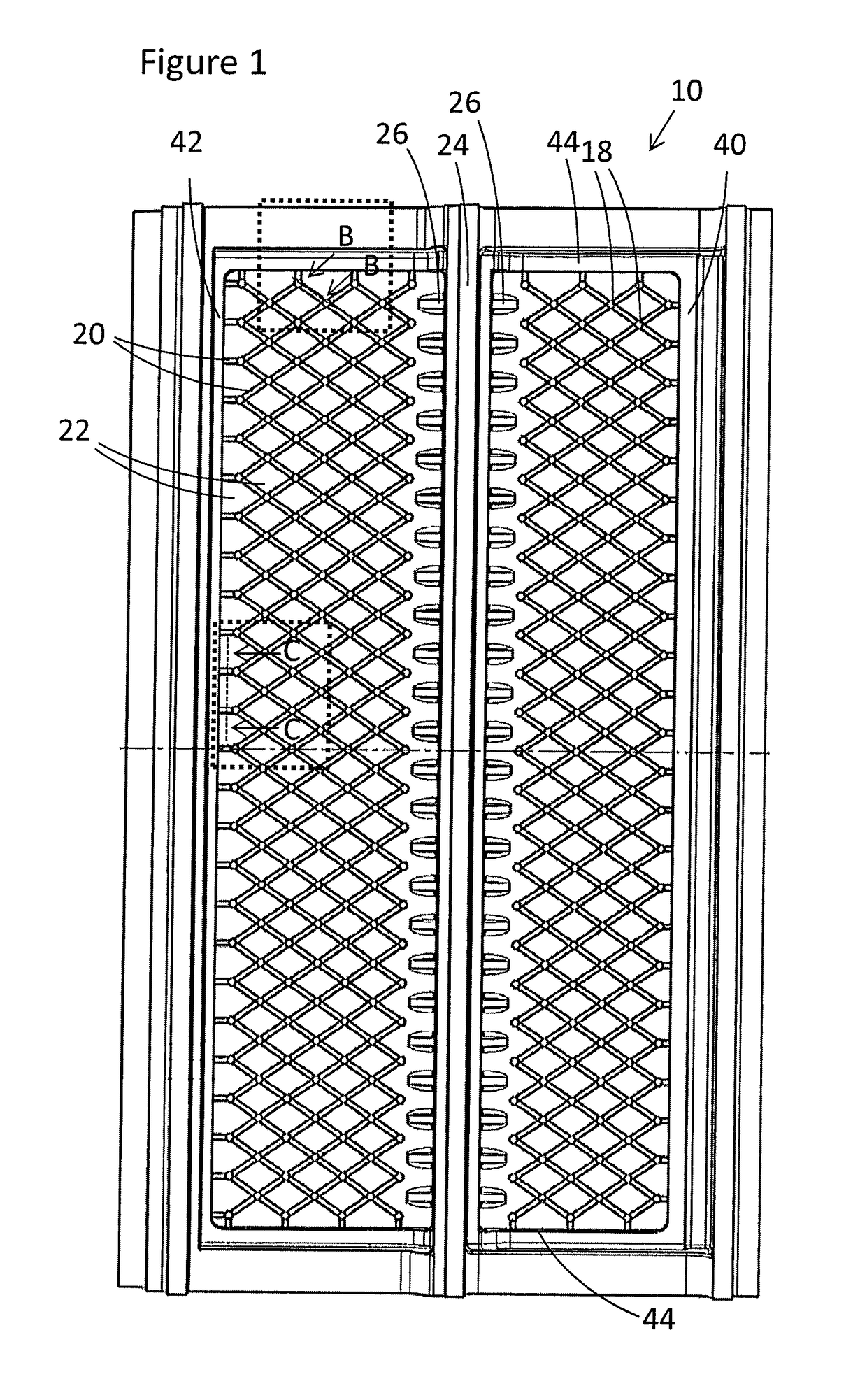
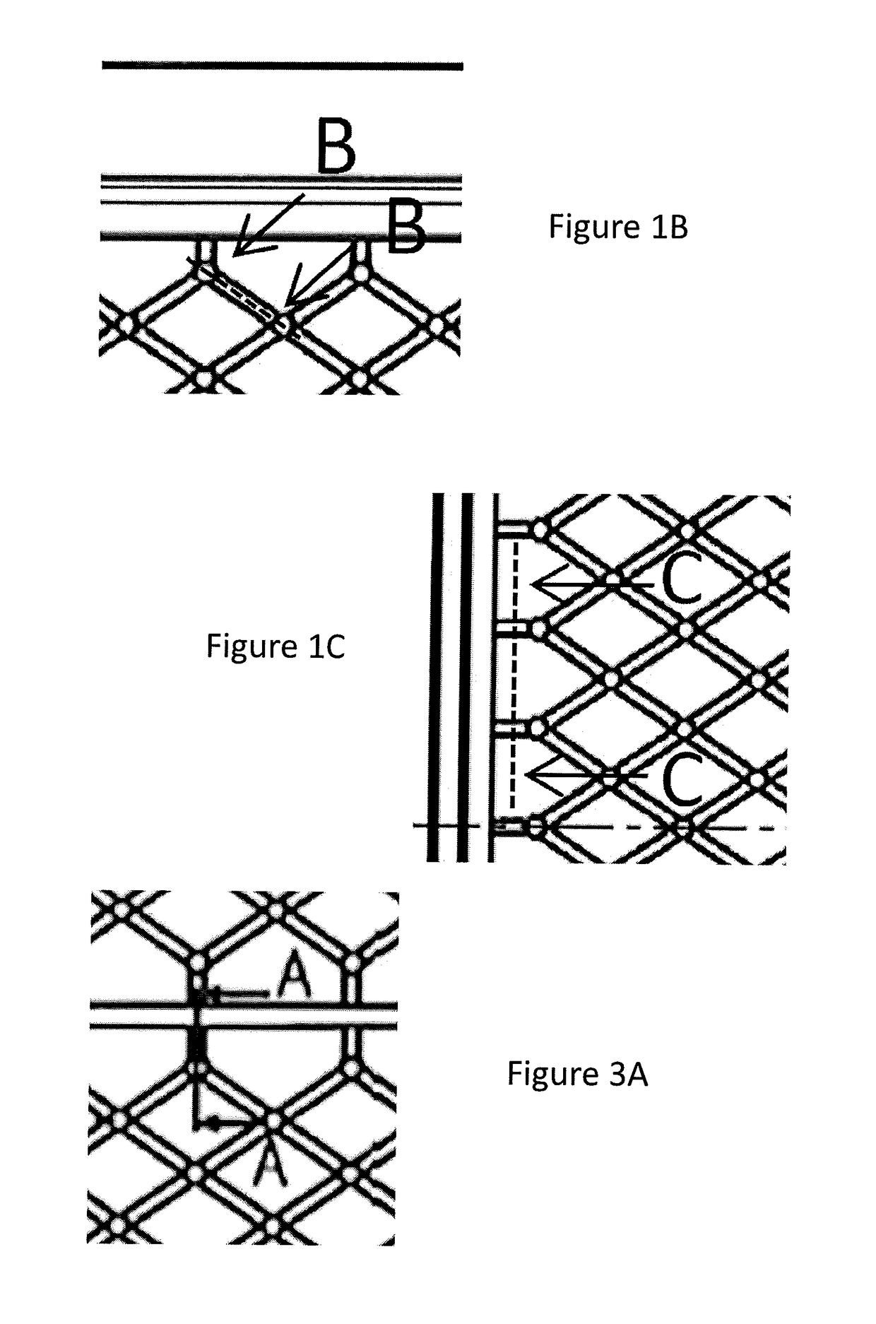
[0026]FIG. 1 and FIG. 2 (a cross-section along B-B in FIG. 1) show a wall 10 for a gas turbine, the wall being for exposure to a hot fluid such as hot exhaust gas on a front side 14. On a back side 16 of the wall, an array of pins 18 is attached. Ribs 20 extend between the pins, and are attached to both the pins and the back wall. The ribs delineate cells 22 on the back side of the wall.

[0027]Optionally, a second wall 24 may be provided, attached to and substantially or completely perpendicular to the back side 16 of the wall. Reinforcement ribs 26 may be attached to the wall and the second wall for structural support.

[0028]FIG. 2 additionally shows an impingement sheet 28, which is added adjacent to the pins. Impingement cooling holes 30 can be provided in the impingement sheet 28. The impingement cooling holes would normally be provided over the centre of a cell 22, so the impingement cooling hole shown in FIG. 2 is actually set back behind the other features shown.

[0029]In FIG. 2...


PUM


Abstract

A wall for a hot gas channel in a gas turbine is described, the wall having a back side and a front side and an impingement sheet having impingement cooling holes, the wall being for exposure to a hot fluid at the front side, and the wall having an array of pins attached to the back side and extending between the back side and the impingement sheet, the wall additionally having a plurality of ribs attached to the back side, each rib extending between two pins to delineate an array of cells on the back side, and / or at least one compartment wall attached to the back side to delineate compartments on the back side. Embodiments include an impingement sheet with impingement cooling holes and cooling exit holes. A gas turbine including the wall is also described.

Description

TECHNICAL FIELD[0001]This invention relates to gas turbines, and particularly to walls for hot gas channels in gas turbines.BACKGROUND OF THE INVENTION[0002]Various parts in gas turbines are subject to high temperatures, and as a result are liable to degrade or disintegrate. One set of such parts is internal hot gas surfaces or walls. These surfaces can be cooled from the back side (cold side) to improve their lifetime. However, lifetime is still limited, and once failure starts to occur (for example a crack), then the part must soon be replaced, as the damage is liable to rapidly spread. This is particularly the case once any crack becomes big enough that significant cooling air is lost through the hole, reducing cooling effectiveness. As an example, an impingement cooled back side allows cracks or openings of a maximum area of the sum of all impingement holes feeding that area in order to remain functional.[0003]It has therefore been appreciated that improvements can be made to pr...

Claims


Application Information

Patent Timeline
Patent Type & Authority Patents(United States)
IPC IPC(8): F01D11/08F02K1/82F01D25/12F01D25/14F23R3/00F28F19/00
CPCF01D25/14F01D25/12F02K1/822F23R3/002F28F19/002F01D11/08Y02T50/675F05D2240/11F05D2240/15F05D2240/81F05D2260/201F05D2260/212F05D2260/22141F23R2900/03044F23R2900/03045F02C7/12Y02T50/60
Inventor DIDION, CHRISTOPHBRANDL, HERBERTCOCHET, MAGALIKOEHNKE, RENE
Owner ANSALDO ENERGIA SWITZERLAND AG
Why Eureka
Try Eureka