Scalable nucleic acid-based nanofabrication

a nucleic acid-based nanofabrication and nucleic acid technology, applied in the direction of nanostructure manufacturing, nanostructure assembly, material nanotechnology, etc., can solve the problem of limited dna chemical stability

Active Publication Date: 2018-10-16
PRESIDENT & FELLOWS OF HARVARD COLLEGE
View PDF41 Cites 7 Cited by
  • Summary
  • Abstract
  • Description
  • Claims
  • Application Information

AI Technical Summary

Benefits of technology

[0005]Provided herein, in some aspects, is a platform that uses substrates such as pre-formed (also referred to as pre-assembled) 2D and / or 3D nucleic acid (e.g., DNA) nanostructures / crystals (e.g., nano- or micro-structures) as global templates for high-resolution fabrication, including programmable nano-manufacturing, of complex 2D and / or 3D architectures from small moieties, such as nanoparticles (e.g., gold nanoparticles) and / or 1D nanowires (e.g., carbon nanotubes or Si nanowires) and / or biomolecules (e.g., proteins and aptamers) at a spatial resolution of at least 1 nm (e.g., 1, 2, 3, 4 or 5 nm, or more). The platform provided herein permits rational integration of, for example, more than 1,000 moieties (homogeneous or heterogeneous populations), into complex prescribed 2D and / or 3D architectures and fundamental one-dimensional (1D) polymeric nanowires and parallel arrays at the aforementioned spatial resolution. The disclosure also provides methods and devices with precision for patterning of at least 0.1 nm across scales from nanometer to wafer scale.
[0008]The present framework differs from existing top-down lithography photolithography / E-beam lithography approaches because of its high-resolution positioning down to 1 nm, and the one-step patterning capability for complex 3D features. Heterogeneous moieties can also be patterned simultaneously. Compared with block copolymer lithography, the nucleic acid-based (e.g., DNA-based) framework provided herein can be used to create complex irregular asymmetric patterns through self-assembly, with minimal feature defects from thermodynamics. The methods and devices formed using such methods as provided herein allow for complicated global architecture, including symmetric and assymetric forms. Using single-layered DNA structures, such as DNA tiles and 2D origami, it is also possible to achieve complex patterns in nano-manufacturing.
[0009]The platform provided herein also permits the construction of complex nano-component-based devices with profound engineering and technological implications. In photonics, for example, coupled nanoparticles direct the light propagation along specific pathways to exchange information or focus energy. In electronics, as another example, particularly for high-density information storage, coupled nanoparticles store multiple information bits at each specific lateral position. With electronics, particularly with high-density information storage medium, well-aligned isolated nanoparticle arrays enable the single-bit addressability down to a 1 nm scale, and more than 1,000 times storage capacity, relative to the current limit. Further, scalable production of crossbar architecture constructed using the platform, as provided herein, enables industry-level production of transistor arrays from nanoribbons or nanowires, which achieves electronic circuits beyond the limit of, for example, current top-down lithography.

Problems solved by technology

The chemical stability of DNA, however, is limited.

Method used


Image

  • Scalable nucleic acid-based nanofabrication
  • Scalable nucleic acid-based nanofabrication
  • Scalable nucleic acid-based nanofabrication

Examples


examples 1

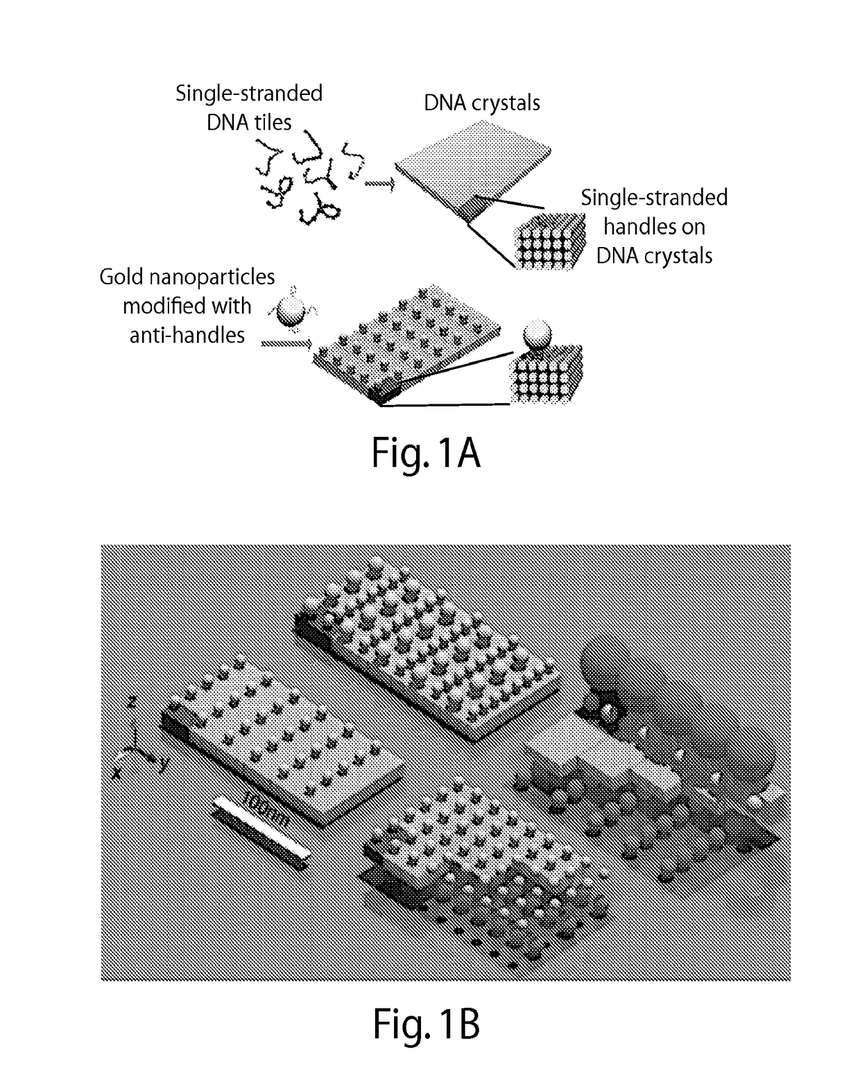
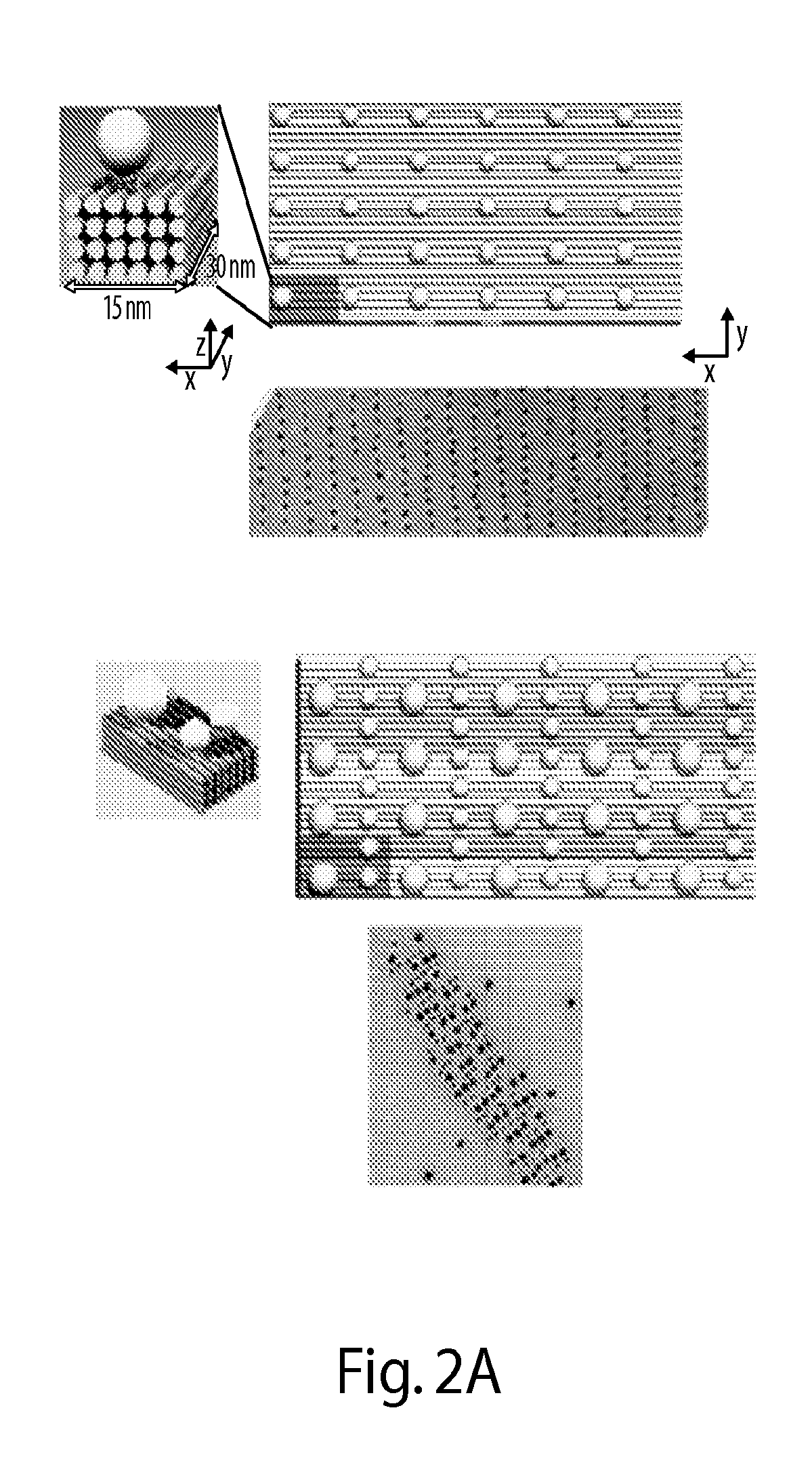
[0305]FIG. 1A illustrates one embodiment of the present disclosure whereby gold nanoparticles chains are aligned in parallel on DNA crystals along the y direction (FIG. 1A). A basic DNA unit cell is designed with x-z cross section of 8 helices by 4 helices and a y-dimensional length of 96 base pairs. This provides a designed x-y periodicity of 15 nm×30 nm, assuming a 2.5 nm helix width and a 0.32 nm per base pair. The repetitive DNA unit cell grows along the x- and y-direction to form the domain composed of four homogeneous sequenced 12-nt single-stranded DNA (ssDNA) handles to capture one gold nanoparticle. Multiple 12-nt anti-handles (a ssDNA with sequence complementary to the handle) are also immobilized onto the gold nanoparticle surface. The hybridization between the handles and the anti-handles anchor the gold nanoparticles onto the prescribed position of DNA crystal. Each gold nanoparticle deviating from the designed position cannot bind to all four handles within a unit cell...

examples 2

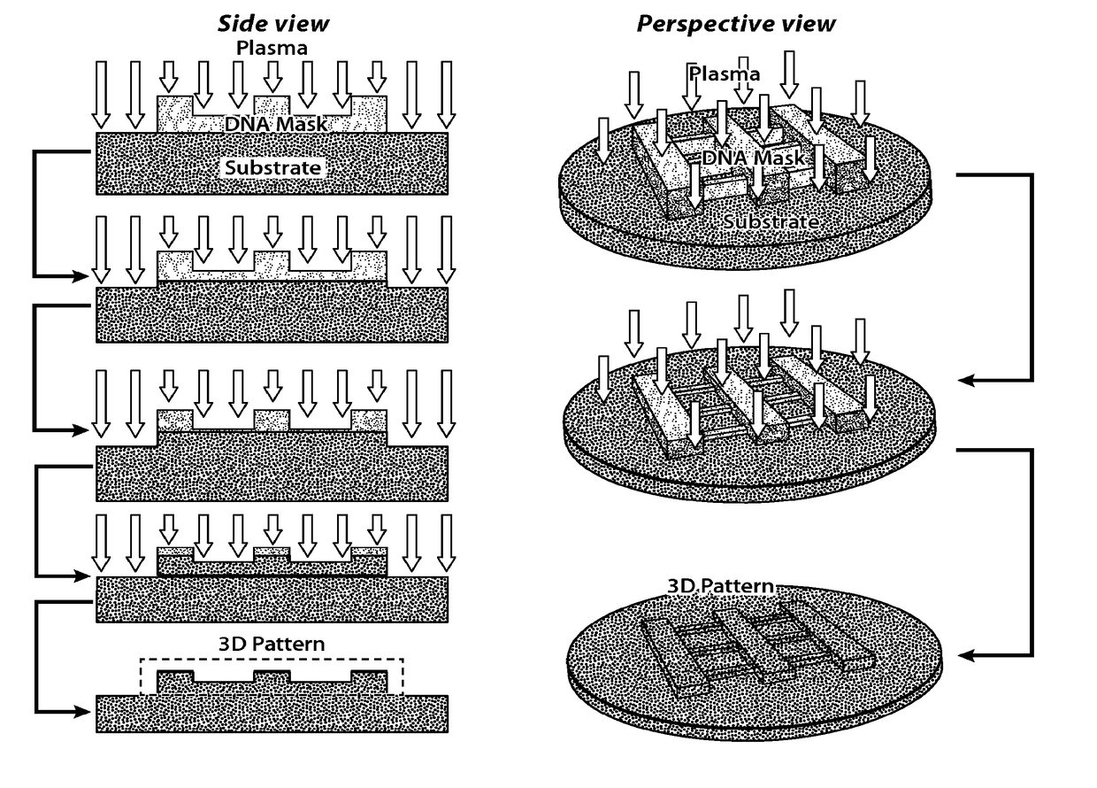
[0309]This Example describes the use of rod-shaped DNA nanostructures (10 nm in width and 2 μm in length) as masks to direct the reactive ion (plasma) etching of inorganic substrates into prescribed linear patterns.

DNA Self-Assembly to Form DNA Rod with 4×4 Helices

[0310]Single-stranded tile (SST) DNA strands were mixed in polymerase chain reaction (PCR) tubes to produce a solution having a final concentration of 1 μM for each strand of DNA. 9 μl of the solution (e.g., comprising or consisting of water) of DNA strands and 1 μl of the folding buffer were combined (final concentration: 0.9 μM SST strands, 5 mM Tris·Cl, pH=7.9 1 mM EDTA, and 40 mM MgCl2). The combined solution was shaken gently to homogenize the solution. The DNA in the solution was annealed in a thermal cycler with a staged isothermal folding for 24 hours using the following the program: 80° C. for 15 minutes, 44° C. for 12 hours, and 39° C. for an additional 12 hours. The resulting DNA nanostructures were rod-shaped (...

examples 3

Deposition of DNA Nanostructure to a Substrate Followed by Desalting and Drying:

[0314]The following example is non-limiting and it is to be understood that a range of nucleic acid nanostructures and substrates and conditions, such as described herein, can be used to effect a similarly desirable result.

[0315]A solution (e.g., 0.5×Tris-ethylenediaminetetraacetic acid (TE) buffer, 40 mM Mg2+; or 100 mM-1 M NaNO3) comprising a bare three-dimensional DNA nanostructure (e.g., 10 pM-1 μM nanostructure concentration, at least 32 base pairs in length) with a depth of 2 nm is adsorbed onto a substrate (e.g., 1 μl-100 μl solution per cm2 substrate), and the solution is permitted to incubate on the substrate (e.g., for 3 minutes to 4 hours) at 4˜25° C. with 50-100% humidity for deposition of DNA nanostructure. Following deposition, the solution is removed (e.g., by wiping and / or by forced air flow) for the subsequent desalting process. The desalting process is applied to remove residual inorgan...


PUM


Abstract

The present disclosure relates to the alignment of moieties (e.g., nanoparticles and / or nanowires) into prescribed architectures on two- and / or three-dimensional substrates (e.g., nucleic acid nanostructures / crystals). The present disclosure also relates to a nucleic acid (e.g., DNA) lithography method that includes, in some embodiments, adsorbing a bare nucleic acid nanostructure onto a surface of a substrate, and etching the surface of the substrate containing the bare nucleic acid nanostructure, thereby producing a patterned substrate.

Description

RELATED APPLICATIONS[0001]This application is a national stage filing under 35 U.S.C. § 371 of international application number PCT / US2015 / 032198, filed May 22, 2015, which was published under PCT Article 21 (21 in English and claims the benefit under 35 U.S.C. § 119(e) of U.S. provisional application No. 62 / 157,595, filed May 6, 2015, U.S. provisional application No. 62 / 079,877, filed Nov. 14, 2014, and U.S. provisional application No. 62 / 002,117, filed May 22, 2014, each of which is incorporated by reference herein in its entirety.FEDERALLY SPONSORED RESEARCH[0002]This invention was made with government support under Contract Nos. N00014-11-1-0914, N00014-10-1-0827 and N00014-13-1-0593 awarded by U.S. Department of Defense Office of Naval Research, under W911NF-12-1-0238 awarded by the U.S. Army Research Office, and under CMMI-1333215 awarded by National Science Foundation. The government has certain rights in the invention.BACKGROUND OF THE INVENTION[0003]Modern electronics and o...

Claims


Application Information

Patent Timeline
Patent Type & Authority Patents(United States)
IPC IPC(8): B82B3/00B82Y5/00B82Y40/00B82Y30/00H01L21/302
CPCB82B3/0047B82Y5/00B82Y40/00B82Y30/00B01J2219/00659
Inventor SHEN, JIESUN, WEIYIN, PENG
Owner PRESIDENT & FELLOWS OF HARVARD COLLEGE
Why Eureka
Try Eureka