Exhaust gas recirculation control device and exhaust gas recirculation control method

a control device and exhaust gas technology, applied in electrical control, machines/engines, mechanical equipment, etc., can solve the problems of difficult pressure on the exhaust side to increase, differential pressure between the exhaust side and the intake side becoming small, and the flow rate is reduced, so as to reduce the amount of intake air, the effect of reducing the flow rate and reducing the pressure loss

Active Publication Date: 2018-10-16
NISSAN MOTOR CO LTD
View PDF11 Cites 0 Cited by
  • Summary
  • Abstract
  • Description
  • Claims
  • Application Information

AI Technical Summary

Benefits of technology

[0004]The target EGR gas amount and the true EGR gas amount easily diverges when the differential pressure between the exhaust side and the intake side is small. Pressure loss decreases with a cooler exhaust system such as an exhaust gas purifying catalyst; for example when the EGR valve opens in a state in which the exhaust system is cooled, the differential pressure between the exhaust side and the intake side is small since the pressure on the exhaust passage is low. Moreover, an exhaust flow rate decreases with a lower intake air amount, and it becomes difficult for the pressure on the exhaust side to increase; as a result, the differential pressure between the exhaust side and the intake side becomes small.
[0005]That is to say, the smaller the intake air amount, the lower the true EGR gas ratio with respect to the target EGR gas ratio, and the possibility that knocking would occur will increase.
[0006]However, the above document does not take the intake air amount into consideration, and sets the same EGR ratio as long as the load is the same, regardless of engine revolution speed. Accordingly, for example, in a low-revolution high-load region, that is, in a region having a low intake air amount although the load is high, knocking occurs more easily due to the divergence between the target EGR gas amount and the true EGR gas amount.
[0007]An object of the present invention is to provide an EGR control device that controls an EGR device in order to be able to prevent an occurrence of knocking even in a state in which divergence between the target EGR ratio and the true EGR ratio may easily occur.

Problems solved by technology

Moreover, an exhaust flow rate decreases with a lower intake air amount, and it becomes difficult for the pressure on the exhaust side to increase; as a result, the differential pressure between the exhaust side and the intake side becomes small.
That is to say, the smaller the intake air amount, the lower the true EGR gas ratio with respect to the target EGR gas ratio, and the possibility that knocking would occur will increase.

Method used


Image

  • Exhaust gas recirculation control device and exhaust gas recirculation control method
  • Exhaust gas recirculation control device and exhaust gas recirculation control method
  • Exhaust gas recirculation control device and exhaust gas recirculation control method

Examples


Embodiment Construction

[0012]Described below is an embodiment of the present invention, with reference to drawings.

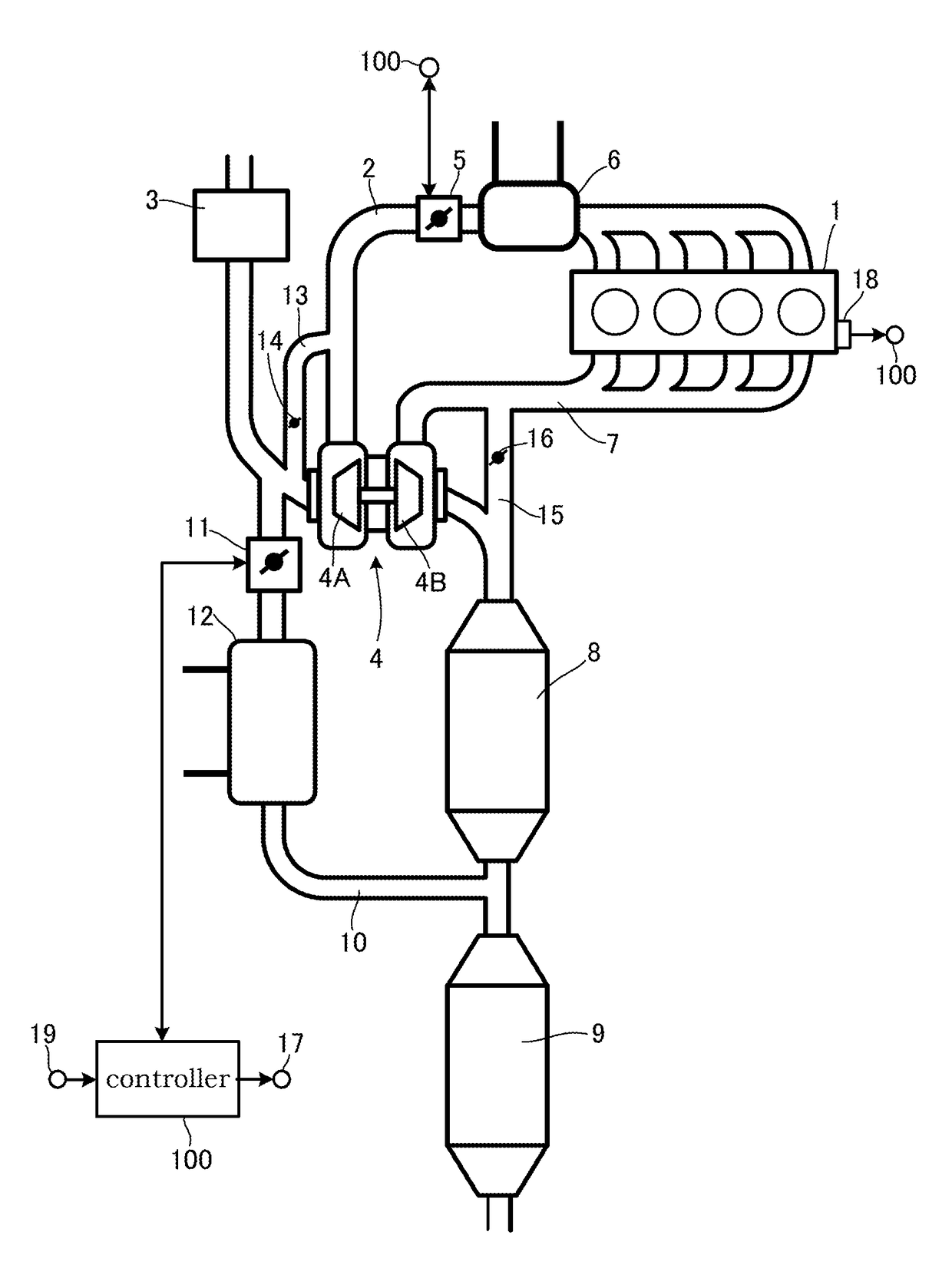
[0013]FIG. 1 is a block diagram of an internal combustion engine system that applies an embodiment of the present invention.

[0014]An intake passage 2 of an internal combustion engine 1 is arranged to have, from upstream of an intake flow, an air flow meter 3, a compressor 4A of a turbo supercharger 4, a throttle chamber 5, and a collector tank 6 integral with intercooler.

[0015]The present system includes a recirculation passage 13 that communicates an upstream side and a downstream side of the compressor 4A, and a recirculation valve 14 that opens when decelerated to return the intake from the downstream side of the compressor 4A to the upstream side thereof.

[0016]Meanwhile, an exhaust passage 7 is arranged to have, from upstream of the exhaust flow, a turbine 4B of the turbo supercharger 4, a manifold catalyst 8, and an underfloor catalyst 9. The present system includes a bypass passage 15 t...


PUM


Abstract

An exhaust gas recirculation control device controls an exhaust gas recirculation device that includes an exhaust gas recirculation passage adapted to circulate a portion of exhaust gas of an internal combustion engine from an exhaust passage downstream of a turbine of a turbo supercharger along an exhaust flow to an intake passage upstream of a compressor of the turbo supercharger along an intake flow and downstream of an air flow meter along the intake flow, and a recirculation control valve adapted to adjust an amount of exhaust gas circulated to the intake passage. Furthermore, the exhaust gas recirculation control device includes recirculation ratio setting means adapted to set a lower target recirculation ratio for a smaller intake air amount of the internal combustion engine.

Description

TECHNICAL FIELD[0001]The present invention relates to an exhaust gas recirculation control device and an exhaust gas recirculation control method, of an internal combustion engine.BACKGROUND ART[0002]There is known an exhaust gas recirculation (EGR: Exhaust Gas Recirculation) device, in which a portion of exhaust gas is recirculated to an intake side to prevent knocking and to improve fuel consumption, in an internal combustion engine. JP2012-512988A defines a percentage of mass of recirculated exhaust gas (EGR gas) entering an intake circuit per unit time with respect to a total mass of air-fuel mixture entering a combustion chamber per unit time as an EGR ratio [%], and discloses a relationship of the EGR ratio with a compression ratio of the internal combustion engine, which is optimum for preventing knocking and improving fuel consumption. More specifically, when a load ratio of the internal combustion engine is of a high load of 50% or more, the relationship is to be of a value...

Claims


Application Information

Patent Timeline
Patent Type & Authority Patents(United States)
IPC IPC(8): F02D41/00F02D41/08F02M26/06F02M26/00F02D41/16F02M26/64F02M26/05
CPCF02D41/0052F02D41/0007F02D41/08F02D41/16F02M26/05F02M26/06F02M26/64F02M26/00Y02T10/121F02D2041/0017Y02T10/12
Inventor TAKAKI, DAISUKETSUCHIDA, HIROFUMISUGAWARA, KAZUHIKO
Owner NISSAN MOTOR CO LTD
Why Eureka
Try Eureka