Eureka AIR delivers breakthrough ideas for toughest innovation challenges, trusted by R&D personnel around the world.

Hydraulic energy absorption device with a displaceable accumulator

a technology of displaceable accumulators and shock absorption devices, which is applied in the direction of shock absorbers, mechanical devices, breech mechanisms, etc., can solve the problems of hydraulic shock absorption devices with stationary accumulators that are more likely to wear and leak, and instability in resistive force, so as to achieve reliable and stable resisting force, increase the bearing length, and control the compression

Active Publication Date: 2018-10-16
KYNTEC
View PDF22 Cites 4 Cited by
  • Summary
  • Abstract
  • Description
  • Claims
  • Application Information

AI Technical Summary

Benefits of technology

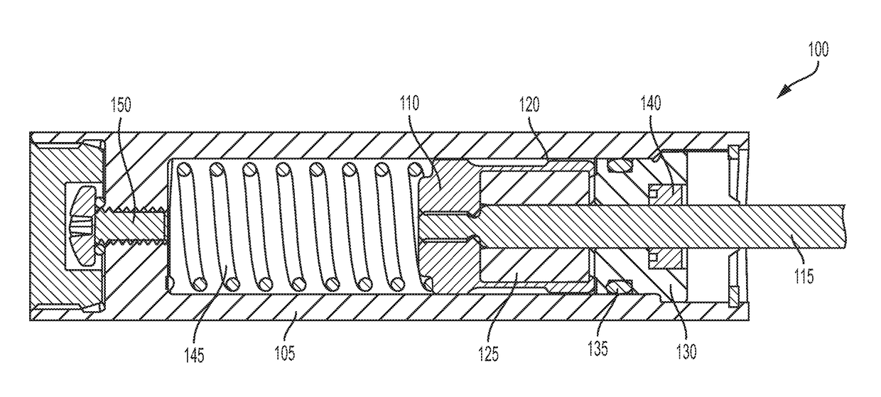
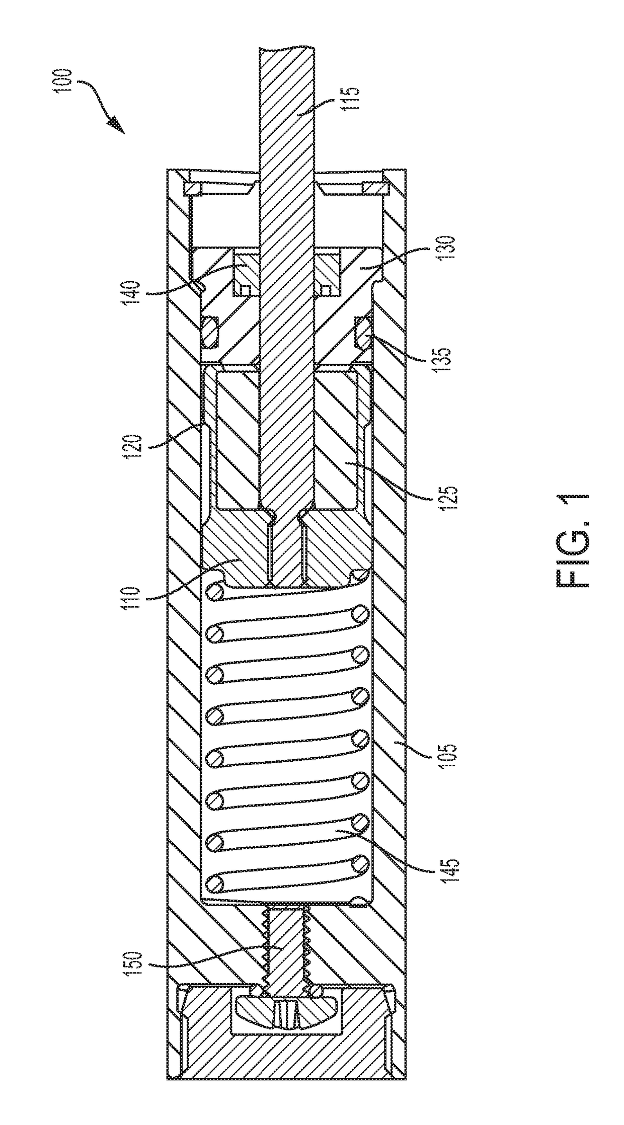
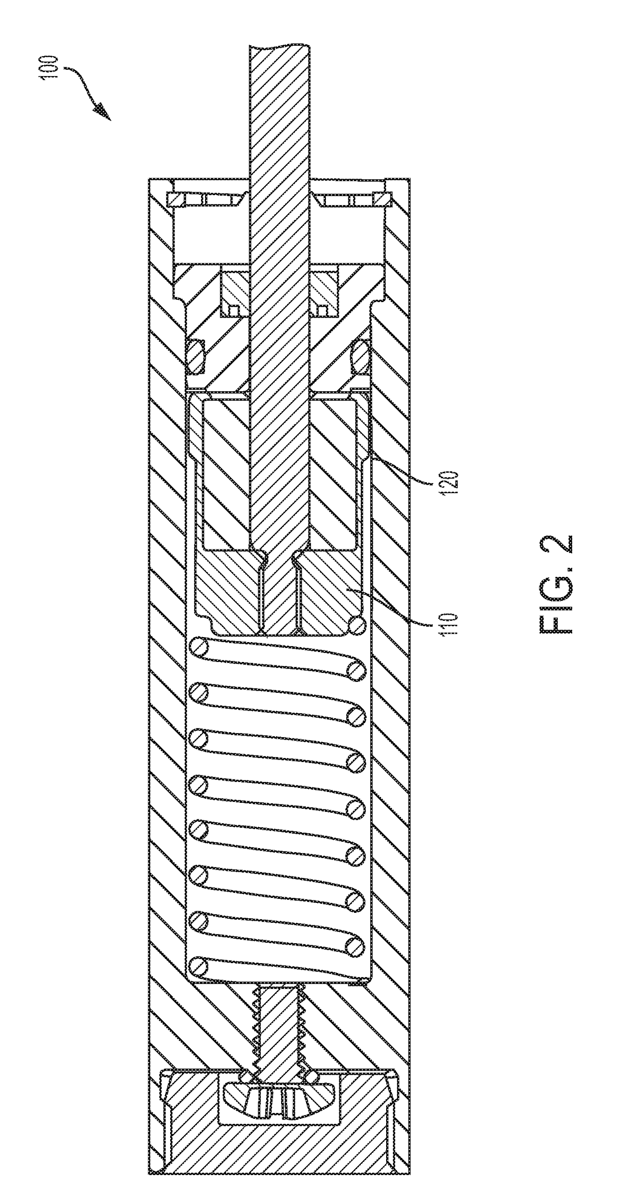
[0005]The present disclosure is directed to inventive devices for recoil buffer and shock absorption that include a moveable accumulator (i.e., is not stationary) along the longitudinal axis of the device. The disclosed designs provide advantages over prior designs by making the device more stable as it is stroked because the bearing length effectively increases, resulting in a more reliable and stable resisting force. Further, because the accumulator travels with the piston head, the compression of the accumulator is more stable and controlled, leading to a consistent / controlled compression of the accumulator. This helps stabilize fluid flow and irregularities associated with uncontrolled flow that an unconstrained open accumulator would have in prior designs. This controlled expansion and compression of the accumulator leads to more stable resistance forces and return forces, longer life, less wear, and reduced high frequency harmonics giving a more stable damping force.

Problems solved by technology

However, hydraulic shock absorbing devices with stationary accumulators have the potential to wear and leak due to a premature failure of the media used for accumulation.
Oil moves at a very high rate into stationary hydraulic chambers, which creates instability in the resistive force as the device's piston rod is stroked as well.
In addition, the length of the bearing that supports the piston rod (and that retains the accumulator) remains constant, which makes the hydraulic shock absorbing device more likely to wear and leak due to the effect of side load caused by the system.
This increases the response time of the accumulator, which creates unstable and harmonic forces as the product is stroked.

Method used


Image

  • Hydraulic energy absorption device with a displaceable accumulator
  • Hydraulic energy absorption device with a displaceable accumulator
  • Hydraulic energy absorption device with a displaceable accumulator

Examples


Embodiment Construction

[0038]A description of example embodiments of the invention follows.

[0039]The example embodiments include an accumulator that is part of (either integral or attached to) a piston head of a recoil buffer or a shock absorber. This allows the recoil buffer or the shock absorber to be more stable as it is stroked because the length of the bearing components of the device is effectively increased during compression, which results in a more reliable and stable resisting force reducing high frequency harmonics. Because the accumulator travels with the piston head, the compression of the accumulator is more stable and controlled, resulting in a consistent / controlled compression, which helps stabilize fluid flow and irregularities associated with uncontrolled flow that an unconstrained open accumulator would have otherwise. This controlled expansion and compression of the accumulator leads to more stable resistance forces. Since the accumulator compression occurs relative to the amount the s...


PUM


Abstract

A hydraulic energy absorption device including a cylindrical housing having an interior hollow compartment, the interior hollow compartment having a distal end and a proximal end, a resilient member arranged within the distal end of the cylindrical housing, a piston arranged adjacent to the resilient member within the cylindrical housing, the piston including a piston head and a piston rod extending from the piston head toward the proximal end and a compressible accumulator arranged within the cylindrical housing and connected to the piston. When the piston rod is displaced toward the distal end of the cylindrical housing in operation, the piston head and the compressible accumulator are displaced toward the distal end of the cylindrical housing.

Description

CROSS-REFERENCE TO RELATED APPLICATIONS[0001]This application claims the benefit of U.S. Provisional Patent Application Ser. No. 62 / 253,814, filed on Nov. 11, 2015 and entitled “Shock Absorber with Floating Accumulator”, the entire disclosure of which is incorporated herein by reference.FIELD OF THE INVENTION[0002]The present disclosure is directed generally to recoil buffer devices and shock absorbing devices, and more specifically, to recoil buffer devices and shock absorbing devices with a displaceable accumulator.BACKGROUND[0003]Hydraulic shock absorbing devices are typically retained in a stationary bearing of the shock absorber. For example, prior hydraulic shock absorbers contain a stationary bearing in a cylindrical housing and retain a stationary accumulator that compensates for excess volume inside the cylindrical housing when a piston rod is introduced into the cylindrical housing.[0004]However, hydraulic shock absorbing devices with stationary accumulators have the poten...

Claims


Application Information

Patent Timeline
Patent Type & Authority Patents(United States)
IPC IPC(8): F16F13/00F41A3/90
CPCF16F13/007F41A3/90F16F2236/04F16F2232/08F41A25/02
Inventor SPYCHE, JR., GERALD JSCHOEN, JOSEPH A
Owner KYNTEC
Why Eureka
Eureka Blog
Learn More