
Multifunctional thermal management system and related method

a multi-functional, thermal management technology, applied in the field of thermal management, can solve the problems of excessive heating and large deflection of the flight deck, unacceptably severe heating of the flight deck and its (organic base) non-skid coating, and achieve the effects of high localized compressive load, high thermal conductivity, and convenient storage, transportation and eventual dissipation of thermal energy

Active Publication Date: 2018-10-23
UNIV OF VIRGINIA ALUMNI PATENTS FOUND
View PDF84 Cites 1 Cited by
  • Summary
  • Abstract
  • Description
  • Claims
  • Application Information

AI Technical Summary

Benefits of technology

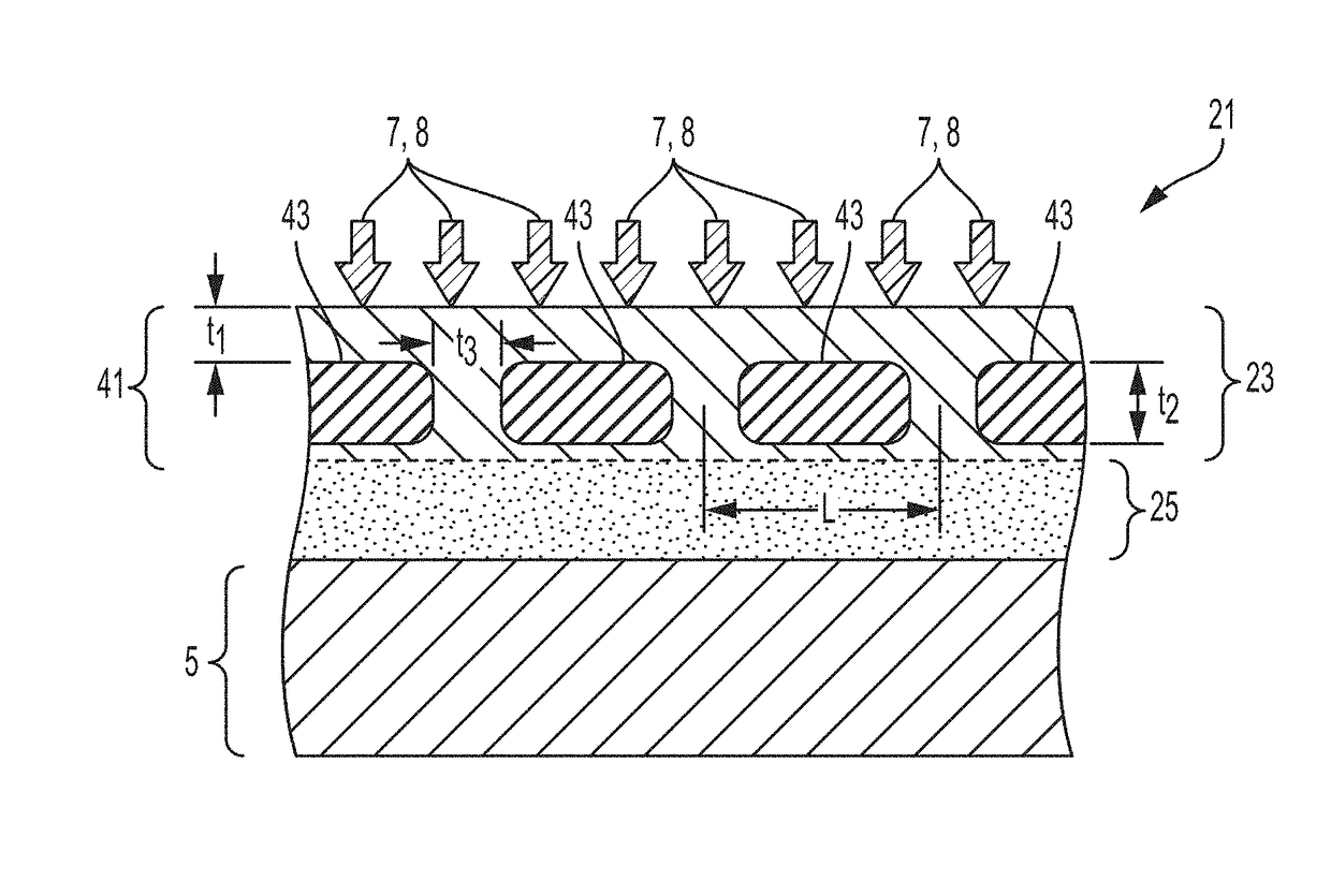
The present invention provides thin thermal management systems that can withstand high compressive loads. The systems use high thermal conductivity materials, heat pipes, and heat plates to store, transport, and dissipate thermal energy. They can be used for protecting surfaces from high thermal and compressive forces or for improving thermal regulation in various applications. The invention also includes an anisotropic thermal management system which has a high thermal conductivity layer for in-plane heat spreading and a low thermal conductivity layer for reducing heat transfer in the direction orthogonal to the high thermal conductivity layer. This system acts as a load-bearing surface or is in communication with a load-bearing surface and facilitates temperature regulation of the area proximal to the low thermal conductivity layer and distal to the high thermal conductivity layer.

Problems solved by technology

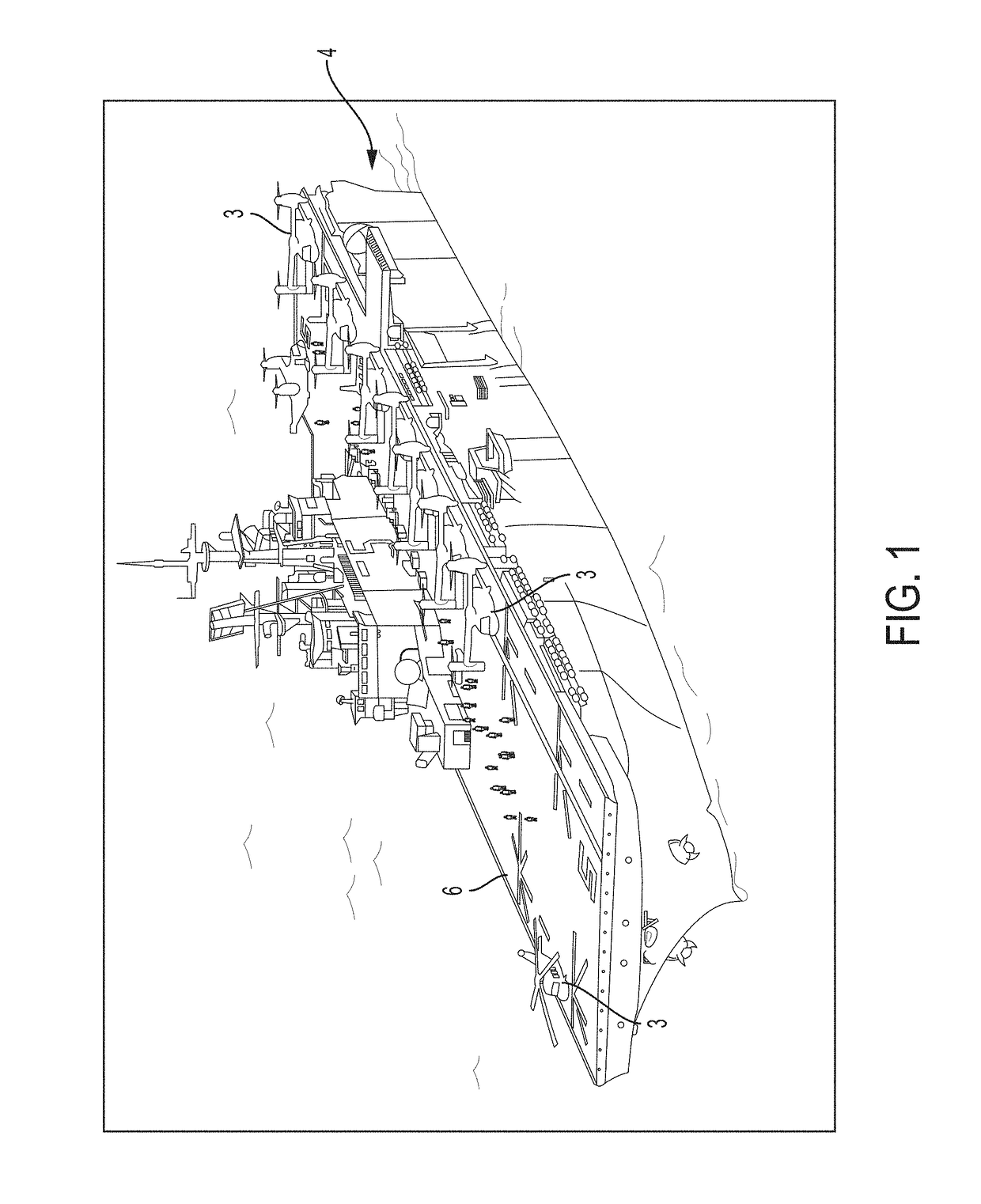
However, the introduction of the MV-22 has to these amphibious assault ships has resulted in flight deck warping during flight operations.
During MV-22 ship integration tests aboard the USS Iwo Jima (LHD 7) in June 2004, there were reports of excessive heating and large deflections of the flight deck in the vicinity of the aircraft's right nacelle.
Subsequent Navy assessments of the thermal loads imposed by the landing of the F-35B Joint Strike Fighter on these ships indicated unacceptably severe heating of the deck and its (organic base) nonskid coating during landing.
This buckling stress results in significant forces applied to the welds between the deck plate and the support structure.
(See Edward L. Davis, Young C. Hwang and David P. Kihl, “Structural Evaluation of an LHD-Class Amphibious Ship Flight Deck Subjected to Exhaust Gas Heat from a MV-22 Osprey Aircraft” NSWCCD-65-TR-2006 / 12 Mar. 2006) indicate that the forces are sufficient to cause local plastic deformation which is likely to result in fatigue failure of the deck before the ship reaches its design life.
Impingement of the high temperature MV-22 and F-35B engine plumes upon this coating is likely to result in its rapid degradation during flight operations and so a new high temperature nonskid coating is required.
However, these coatings are susceptible to delamination during severe thermal cyclic loading and have low strengths.
Heretofore the prior art has failed to be able to adequately dissipate or protect the ship decks from the exhaust of high temperature plumes of jet craft.
Moreover, regarding buildings, structures and housings, the prior art has failed to be able to efficiently minimize or contain the additional energy expenditure necessary to transfer heat or cooling to intended areas of the buildings, structures, housings or areas.
Existing heating and cooling systems for buildings, structures, and housing are also structurally parasitic, since they require architectural accommodation to provide the necessary space and support.

Method used


Image

  • Multifunctional thermal management system and related method
  • Multifunctional thermal management system and related method
  • Multifunctional thermal management system and related method

Examples


examples

[0081]Practice of an aspect of an embodiment (or embodiments) of the invention will be more fully understood from the following examples and experimental results, which are presented herein for illustration only and should not be construed as limiting the invention in any way.

[0082]When the MV-22 Osprey is in its helicopter mode, there are two downward components of air flow impinging on the flight deck: hot exhaust gases from the jet engine and ambient temperature air from the aircraft's rotors. Both of these flows impinge upon the flight deck vertically and the streamlines are then directed radially outwards. Because the air flow induced by the aircraft's propellers is much lower than the hot exhaust air flow, it provides a potential source of cooling for the flight deck. The same is true for the F-35B's lift-fan air.

[0083]In certain landing pad and flight deck embodiments, proposed solutions rely on exploiting the air outside the jet exhaust plume to reduce the heat deposited int...


PUM

PropertyMeasurementUnit
Thicknessaaaaaaaaaa
Electrical conductivityaaaaaaaaaa
Structureaaaaaaaaaa

Abstract

A system and related method that provides, but is not limited thereto, a thin structure with unique combination of thermal management and stress supporting properties. An advantage associated with the system and method includes, but is not limited thereto, the concept providing a multifunctional design that it is able to spread, store, and dissipate intense thermal fluxes while also being able to carry very high structural loads. An aspect associated with an approach may include, but is not limited thereto, a large area system for isothermalizing a localized heating source that has many applications. For example it can be used to mitigate the thermal buckling of ship deck plates, landing pad structures, or any other structures subjected to localized heating and compressive forces. It can also be used as a thermal regulation system in numerous applications, including but not limited to under-floor heating for residential or commercial buildings or for the de-icing of roads, runways, tunnels, sidewalks, and bridge surfaces.

Description

RELATED APPLICATIONS[0001]The present application is a national stage filing of International Application No. PCT / US2011 / 021121, filed 13 Jan. 2011, which claims priority under 35 U.S.C. § 119(e) from U.S. Provisional Application Ser. No. 61 / 295,112, filed Jan. 14, 2010, entitled “A Multifunctional Heat Pipe Solution to Plate Thermal Buckling and Related Method,” the disclosures of which are hereby incorporated by reference herein in their entirety.FIELD OF THE INVENTION[0002]The present invention relates generally to the field of thermal management. More specifically, the present invention also relates to thermal conduction, heat capacity, heat pipe systems, and phase change materials.BACKGROUND OF THE INVENTION[0003]Amphibious Assault Ships support US Marine Corps expeditionary forces for extended periods of time. They in some ways resemble small aircraft carriers and are capable of supporting both Marine air and rotorcraft and a variety of amphibious vehicles. The landing helicop...

Claims


Application Information

Patent Timeline
IPC IPC(8): F24H3/00F28D15/02F24D19/02F28D15/04F28D20/02E01C11/26F02M31/08F24F13/00
CPCF28D15/046E01C11/26F28D20/02F28D15/0275Y10T29/49353Y02E60/145Y02E60/14
Inventor WADLEY, HAYDN N. G.HAJ-HARIRI, HOSSEINZOK, FRANKNORRIS, PAMELA M.
Owner UNIV OF VIRGINIA ALUMNI PATENTS FOUND
Learn More