
Transformational architecture for multi-layer systems

a technology of transformational architecture and multi-layer systems, applied in data switching networks, instruments, digital transmission, etc., can solve the problems of increasing the layer count of the pcbs, increasing the complexity of routing and power dissipation, and significant amount of power dissipation, so as to achieve efficient multi-port network switching

Active Publication Date: 2018-10-23
OPTEL NETWORKS INC
View PDF4 Cites 2 Cited by
  • Summary
  • Abstract
  • Description
  • Claims
  • Application Information

AI Technical Summary

Benefits of technology

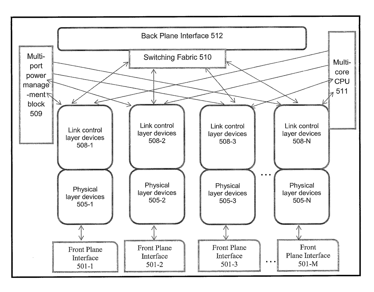
The new architecture is a system that helps networks handle more traffic efficiently by using advanced technology to integrate optics and electronics on a single substrate. This system uses multi-core computing to handle open network protocols and is designed to eliminate many layers of circuitry and improve port configurability. It also helps to provision bandwidth and switch between different functions in a scalable and low-power manner. Overall, this new architecture provides better performance and flexibility for multi-port networking cards.

Problems solved by technology

But this component supply and manufacturing ecosystem forced the industry to adopt only certain types of partitioning design with discrete components and external interfaces.
In a multi-layer printed circuit board (PCB) embodiment of a network card, transmission lines between the PCB layers lead to significant amount of power dissipation.
High density nature of the PCBs with numerous ports operating at 10 Gb / s and beyond leads to dense and longer trace lengths adding significant routing complexity and power dissipation.
The routing complexity is the leading cause of increase in layer count in the PCBs.
This leads to enormous board complexity impacting manufacturing yields and quality and / or reliability of the systems.

Method used


Image

  • Transformational architecture for multi-layer systems
  • Transformational architecture for multi-layer systems
  • Transformational architecture for multi-layer systems

Examples


Embodiment Construction

[0014]Embodiments will now be described in detail with reference to the drawings, which are provided as illustrative examples so as to enable those skilled in the art to practice the embodiments. Notably, the figures and examples below are not meant to limit the scope to a single embodiment, but other embodiments are possible by way of interchange of some or all of the described or illustrated elements. Wherever convenient, the same reference numbers / labels will be used throughout the drawings to refer to same or like parts. Where certain elements of these embodiments can be partially or fully implemented using known components, only those portions of such known components that are necessary for an understanding of the embodiments will be described, and detailed descriptions of other portions of such known components will be omitted so as not to obscure the description of the embodiments. In the present specification, an embodiment showing a singular component should not be consider...


PUM


Abstract

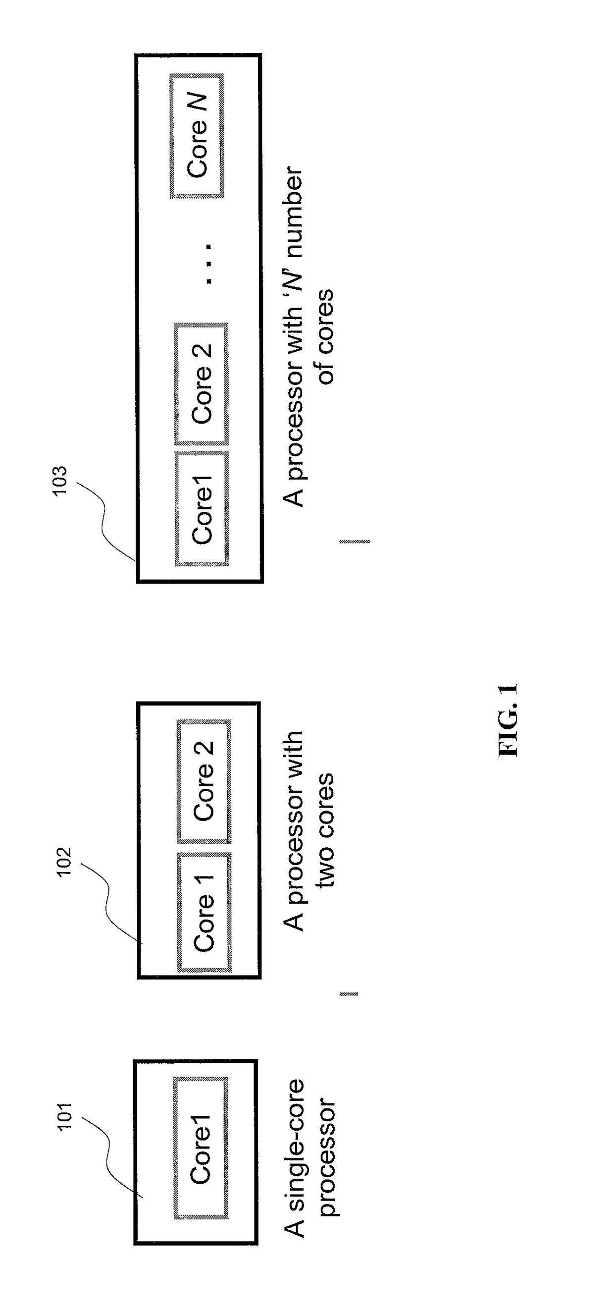
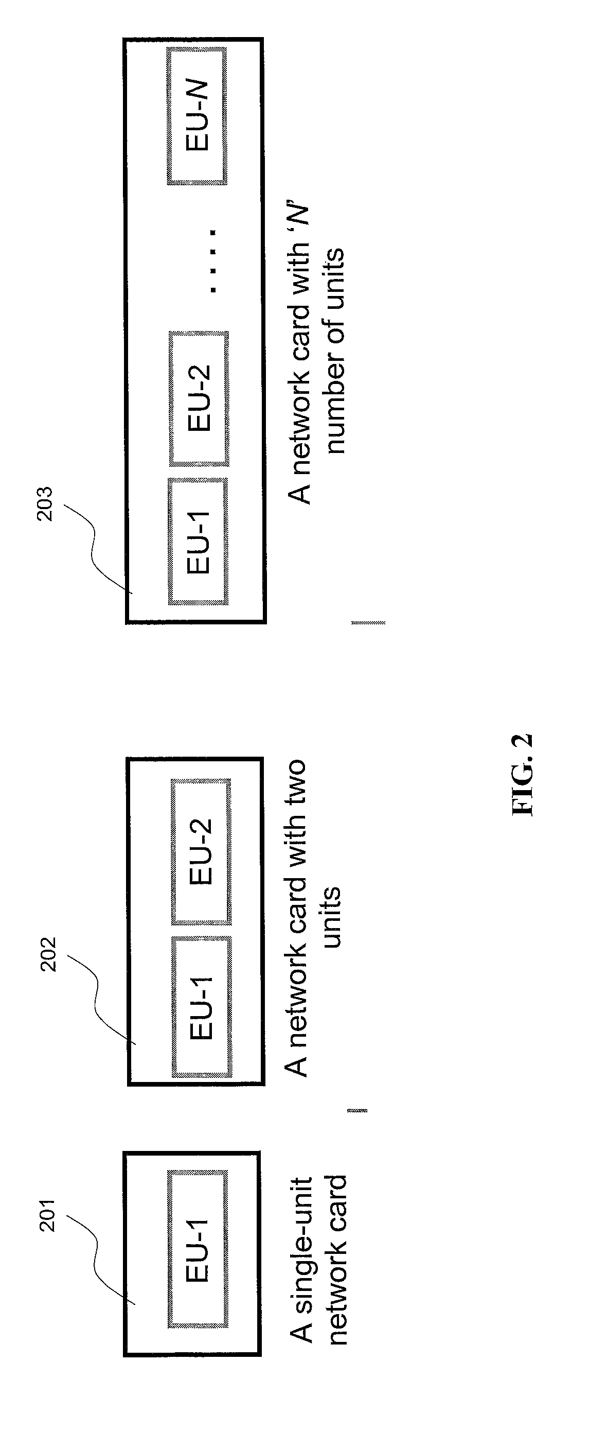
The new architecture disclosed herein exploits advances in system and chip technologies to implement a scalable multi-port open network. Using System-on-a-Chip (SOCs) and / or Multi-Chip-Module (MCM) technology, the architecture is implemented to efficiently handle multi-port switching. The novelty lies in using multi-core computing model in the data, control and management planes of multi-port networking cards implemented as an elemental scalable system (ESS) comprising N number of Elemental Units (EUs). EUs comprise device arrays on an integrated circuit (IC) platform using integrated silicon photonics or discrete electro-optics. TX4M™ system architecture therefore includes multiple EUs, switch fabric, multi-core central processing unit (CPU), multi-port power management module with embedded programmable logic, a back plane interface (BPI) as well as selectable functions for front plane interface (FPI) implemented in FPGAs for integration of front plane interface optics on host or on pluggable modules.

Description

CROSS-REFERENCE TO RELATED APPLICATIONS[0001]This application claims the benefit under 35 USC 119(e) of prior U.S. Provisional Patent Application No. 62 / 004,726, filed May 29, 2014, the disclosure of which is hereby incorporated by reference in its entirety.FIELD OF THE DISCLOSURE[0002]This disclosure relates to an improved and condensed architecture for multi-layer open networks. Applications include data communication and telecommunication network applications, as well as consumer and defense applications. Particular application includes access, aggregation and core multi-tier design for data centers. Specifically, this disclosure addresses how system cards are architected and partitioned at the lower layers of the communication protocol for multi-port datacom, telecom, cloud computing networks, and other computer networks for consumer and defense applications.BACKGROUND OF THE RELATED ART[0003]Multi-layer open networking models, such as the seven-layer Open System Interconnection...

Claims


Application Information

Patent Timeline
Patent Type & Authority Patents(United States)
IPC IPC(8): G06F13/40G06F13/42
CPCG06F13/4022G06F13/4221G06F13/385G06F2213/3808H04L12/2803Y02D10/00H04L12/00
Inventor MANOHAR, AMAR S.
Owner OPTEL NETWORKS INC
Learn More