Photovoltaic modules with corner junction boxes and array of the same

a photovoltaic module and junction box technology, applied in the field of photovoltaic modules and photovoltaic arrays, can solve the problems of increasing the risk of wire and its insulation breaking, affecting the operation and presenting practical challenges in the management of the pv module wiring, so as to achieve the effect of ensuring connection tension

Active Publication Date: 2018-10-30
TESLA INC
View PDF10 Cites 1 Cited by
  • Summary
  • Abstract
  • Description
  • Claims
  • Application Information

AI Technical Summary

Benefits of technology

[0004]The present disclosure provides for photovoltaic (PV) modules that break apart the typical junction box on the back of a PV module into positive-voltage (V+) negative voltage (V−) junction boxes, in order to enable the use of shorter lengths of wire, faster installation processes, and more efficient wire management. The present disclosure allows for a single type of PV module needed for any given solar panel array, where successive rows are configured to be electrically connected when oriented in opposite directions from each other.
[0006]The use of separated junction boxes located at the corners of the PV modules as considered herein can reduce the amount of wiring that is needed to form a string or array of PV modules. Instead of wiring that extends half a length or half a width of a PV module (or more), because the separated junction boxes are located at the corners of the PV modules, when PV modules are arranged adjacent to each other in a row as part of a string, the corresponding junction boxes are located right next to each other. By configuring each PV module to have the respective positive-voltage junction box and negative-voltage junction box in the same corners on the same edge of the PV module, when such PV modules are arranged horizontally adjacent to each other in the same orientation, the positive-voltage junction box of a first PV module will be positioned next to the negative-voltage junction box of an adjacent second PV module. Similarly, the negative-voltage junction box of the first PV module will be positioned next to the positive-voltage junction box of an adjacent third PV module (on the opposite side of the first PV module). As used herein, positive-voltage junction boxes and negative-voltage junction boxes can be referred to collectively as corner junction boxes.
[0007]Due to the relatively proximity of adjacent positive-voltage junction boxes and negative-voltage junction boxes on separate PV modules in the same row of a string or array, the wiring needed to electrically connect two such PV modules can be minimized to a length, for example, that covers the distance from a corner junction box to the edge of a PV module, the gap between the PV module and an adjacent PV module, and the distance from the edge of the adjacent PV module to the corner junction box on that adjacent PV module. Current junction boxes are about one meter (1 m) long. In such installations, the length of wire can be selected to be relative taught, or to have sufficient tension such that the wiring connection does not have an amount of slack that necessitates the use of wiring clips to secure the wire to either PV modules. The relatively short length and uncomplicated wiring path from one corner junction box to an adjacent corner junction can provide for both a quicker installation process and less expensive PV modules than with traditional junction boxes known in the field.
[0008]Moreover, by reducing or eliminating the need to bend wiring elements extending from junction boxes due to the close proximity of corner junction boxes to each other, the wiring extending from positive-voltage junction boxes and negative-voltage junction boxes can extend at a most advantageous angle (e.g. straight) for function and reliability of the wiring as part of a photovoltaic string or array.
[0009]For connecting PV modules in successive rows of a string or array (e.g. connecting one row of PV modules to a subsequent row of PV modules further up or “north” on a roof) the arrangement and orientation of PV modules can continue to provide for an efficient and minimal use of wiring. In an exemplary embodiment for any given roof or installation, a first row of PV modules can be oriented in the same direction, with a positive-voltage junction box located at the “upper” right-side corner of each PV module and a negative-voltage junction box located at the “upper” left-side corner of each PV module. A second row of PV modules, arranged above the first row of PV modules, can be oriented in the opposite direction relative to the first row of PV modules (or in other word, 180° away from the orientation of the first row). In this opposite orientation, with the corner junction boxes configured in the same locations, the “upper” side of a PV module becomes in effect a lower edge, such that at one lateral end of the two rows, a positive-voltage junction box and a negative-voltage junction box can be electrically connected with a relatively short or minimal amount of wiring, similar to how adjacent PV modules in the same row are connected.
[0012]In some embodiments, the corner junction boxes can have retractable wiring functionality, such that once a corner junction box on a first PV module is connected to a corner junction box of an adjacent PV module, the amount of wiring that is slack can be retracted into the corner junction box, thereby providing for tension of the connection and mitigating the need for any wiring clips or similar wire management couplings. In some embodiments, the PV modules can be constructed such that only positive-voltage junction boxes have wiring, such that wiring extends from the positive-voltage junction box of a PV module to a receiving outlet on a negative-voltage junction box on an adjacent PV module. In other embodiments, the PV modules can be constructed such that only negative-voltage junction boxes have wiring, such that wiring extends from the negative-voltage junction box of a PV module to a receiving outlet on a positive-voltage junction box on an adjacent PV module. In further embodiments, PV modules can be constructed such that both positive-voltage junction boxes and negative-voltage junction boxes have wiring components, configured to connect with each other, such that wiring extends from either or both of the positive-voltage junction box of a PV module to wiring extending from a negative-voltage junction box on an adjacent PV module, meeting in between the two corner junction boxes.

Problems solved by technology

Management of PV module wiring can present practical challenges.
In several situations, the wiring extending from the junction box must be bent around physical conflicts, often bending close to the junction box such that the installation is difficult to fit at the location of the junction box, and / or the wire is forced to bend sharply in a manner that may wear down or increase a breaking risk of the wire and its insulation, or even degrade the maximum or peak amount of current the wire can conduct.
Further, each junction box can be a hotspot on the PV module, where the electricity collected at the center of the PV module can raise the temperature of the PV module at a localized region, risking a loss of efficiency or adverse effect on function of the PV module due to the relatively increased heat profile at or near the junction box.

Method used


Image

  • Photovoltaic modules with corner junction boxes and array of the same
  • Photovoltaic modules with corner junction boxes and array of the same
  • Photovoltaic modules with corner junction boxes and array of the same

Examples


Embodiment Construction

[0025]Throughout this description for the purposes of explanation, numerous specific details are set forth in order to provide a thorough understanding of the many aspects and embodiments disclosed herein. It will be apparent, however, to one skilled in the art that the many aspects and embodiments may be practiced without some of these specific details. In other instances, known structures and devices are shown in diagram or schematic form to avoid obscuring the underlying principles of the described aspects and embodiments.

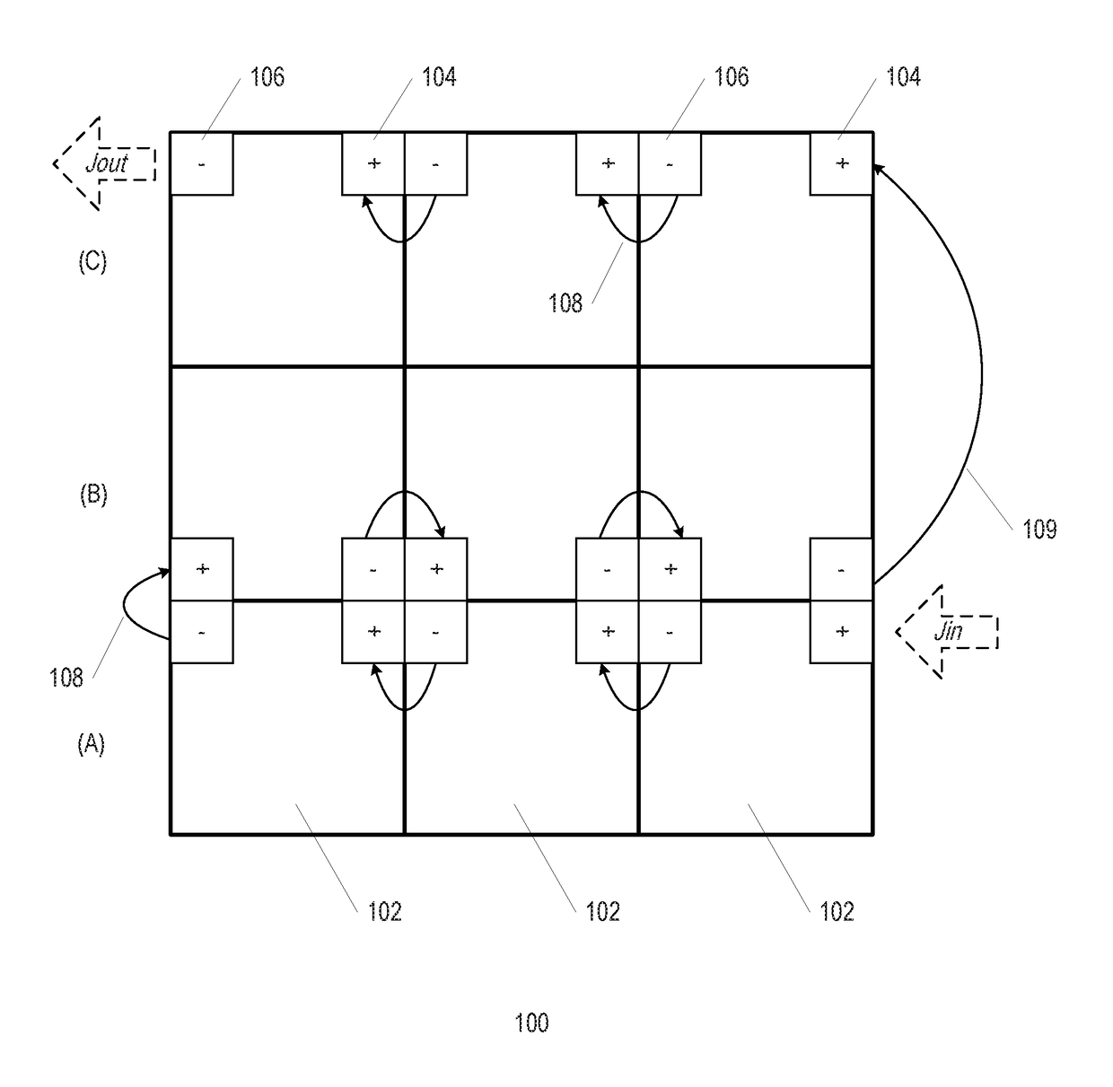
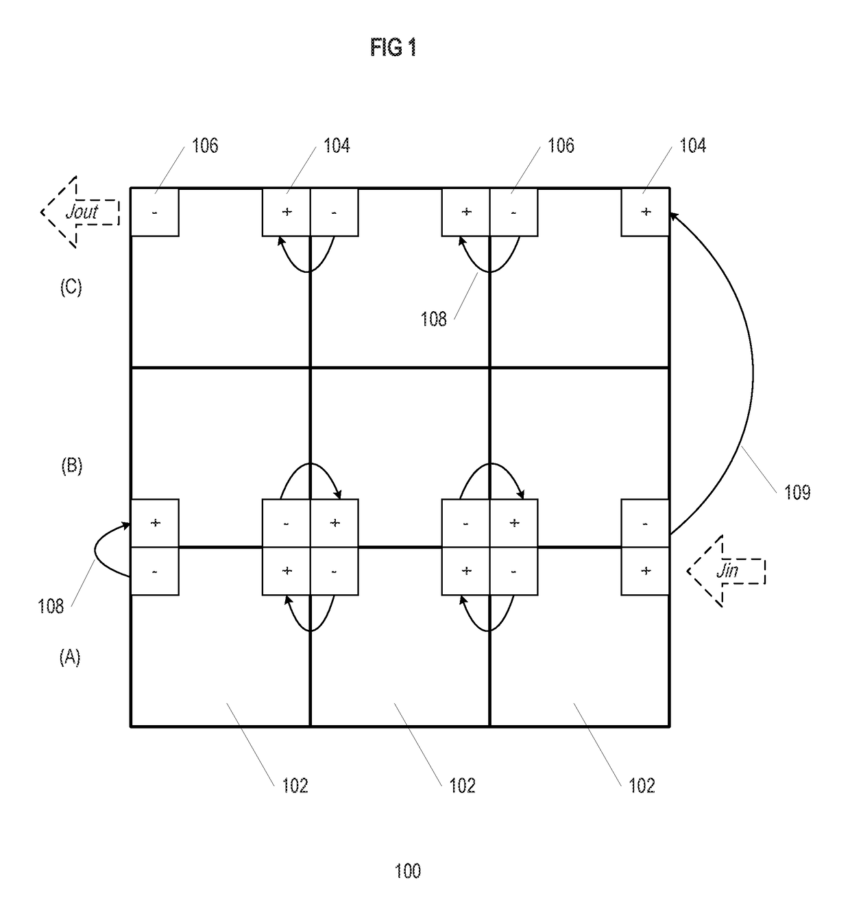
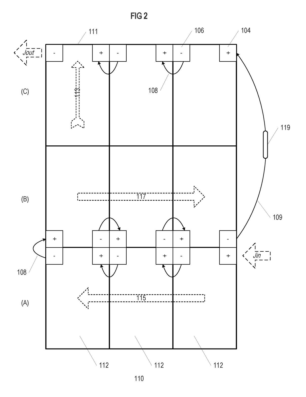
[0026]The present invention discloses photovoltaic (PV) modules having separate and distinct positive-voltage (V+) negative voltage (V−) junction boxes instead of traditional combination junction boxes, on the underside or back of the PV module. Traditional junction boxes tend to be located toward the center of a PV module closer to one end, thus wiring connections between adjacent PV modules forming a string of PV modules as part of a solar panel array require ...


PUM


Abstract

Photovoltaic modules are constructed having separate positive and negative junction boxes positioned at the corners of each photovoltaic module. A photovoltaic array assembled from these photovoltaic modules can be aligned such that the positive and negative junction boxes connect in an arrangement that minimizes the amount of wire needed to install the photovoltaic array. The arrangement of photovoltaic modules connecting the positive and negative junction boxes on adjacent photovoltaic modules leads to successive rows of photovoltaic modules in the photovoltaic array are oriented in opposing directions.

Description

TECHNICAL FIELD[0001]The present invention relates to photovoltaic modules and photovoltaic arrays assembled therefrom.BACKGROUND OF THE INVENTION[0002]Photovoltaic modules generally have a single junction box located on the back side, which takes the electicity generated by the photovotaic module and splits the electicity into positive and negative (V+ and V−), such that the photovoltaic module can be connected to other electical elements as part of a circuit (e.g., other modules, an interter, a micro inverter, etc.). Such junction boxes tend to be centrally located on the underside of photovoltaic modules, which can present physical conflict problems with other components of a solar panel array installation, can lead to complex or disadvantageous wiring paths, and can be susceptible to generating hotspots disadvantageous to the operation of the photovoltaic module.[0003]Accordingly, there is a need for photovoltaic module configurations that diverge from traditional junction box l...

Claims


Application Information

Patent Timeline
Patent Type & Authority Patents(United States)
IPC IPC(8): H01L31/00H02S40/34H02S40/36
CPCH02S40/36H02S40/34Y02E10/50
Inventor MILJKOVIC, DAVIDATCHLEY, BRIANWEST, JACK RAYMONDDE VRIES, NICHOLAS G. J.
Owner TESLA INC
Why Eureka
Try Eureka