Dynamic analysis system and analysis device

a dynamic analysis and analysis system technology, applied in the field of dynamic analysis systems and analysis devices, can solve the problems of long examination time, unfavorable gas exchange, and a great strain on patients, and achieve the effect of high accuracy

Active Publication Date: 2018-12-11
KONICA MINOLTA INC
View PDF4 Cites 5 Cited by
  • Summary
  • Abstract
  • Description
  • Claims
  • Application Information

AI Technical Summary

Benefits of technology

[0009]Objects of the present invention include calculating the V / Q ratio with high accuracy by using a dynamic chest image.

Problems solved by technology

If one or both of the functions deteriorates, gas exchange does not work well.
However, they require patients to take in radioisotopes and therefore put a great strain on the patients, and also their examination time is long.
Therefore, the V / Q ratio cannot be calculated with high accuracy.

Method used


Image

  • Dynamic analysis system and analysis device
  • Dynamic analysis system and analysis device
  • Dynamic analysis system and analysis device

Examples


first embodiment

[Configuration of Dynamic Analysis System 100]

[0029]First, the configuration of a first embodiment is described.

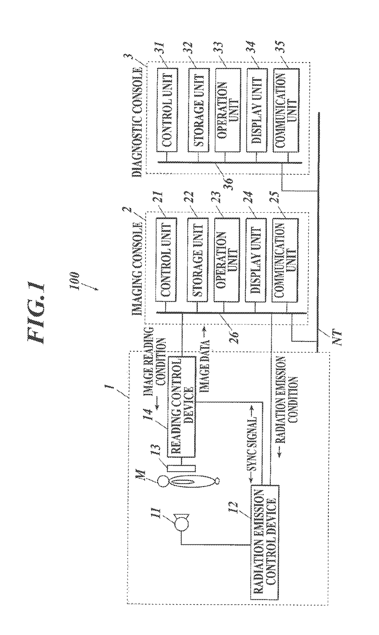
[0030]FIG. 1 shows the overall configuration of a dynamic analysis system 100 according to the embodiment(s) of the present invention.

[0031]As shown in FIG. 1, the dynamic analysis system 100 includes: an imaging device 1; an imaging console 2 connected with the imaging device 1 via a communication cable or the like; and a diagnostic console 3 connected with the imaging console 2 via a communication network NT, such as a LAN (Local Area Network). The devices or the like of the dynamic analysis system 100 are in conformity with DICOM (Digital Image and Communications in Medicine) standard and communicate with each other in conformity with DICOM.

[Configuration of Imaging Device 1]

[0032]The imaging device 1 is an imaging unit which images a cyclic dynamic state of a chest part. Examples of the cyclic dynamic state include: change in shape of the lungs, i.e., expansion and con...

second embodiment

[0086]Hereinafter, a second embodiment of the present invention is described.

[0087]The configurations (and components) and the imaging actions in the second embodiment are the same as those described in the first embodiment. Therefore, the descriptions thereof are not repeated here, and actions of the diagnostic console 3 in the second embodiment are described.

[0088]In the diagnostic console 3, when receiving a series of frame images of a dynamic image from the imaging console 2 through the communication unit 35, the control unit 31 performs a V / Q ratio calculation process B shown in FIG. 10 in cooperation with the program stored in the storage unit 32.

[0089]FIG. 10 is a flowchart of the V / Q ratio calculation process B performed by the control unit 31 of the diagnostic console 3 in the second embodiment.

[0090]First, the control unit 31 selects an analysis range from a series of frame images of a dynamic image (Step S21). Selection of the analysis range in Step S21 is the same as tha...


PUM


Abstract

A dynamic analysis system includes an imaging device and an analysis device. The imaging device performs dynamic imaging by emitting radiation to a chest part of a human body, thereby obtaining a series of frame images showing a dynamic state of the chest part. The analysis device includes a controller. The controller (i) selects a first plurality of frame images to be analyzed from the series of frame images obtained by the imaging device, (ii) calculates, based on the first plurality of frame images, a ventilation amount index value that indicates an amount of ventilation of a lung field and a perfusion amount index value that indicates an amount of perfusion of the lung field, and (iii) calculates a ratio of the ventilation amount index value to the perfusion amount index value.

Description

CROSS-REFERENCE TO RELATED APPLICATIONS[0001]This application is based upon and claims the benefit of priority under the Paris Convention of Japanese Patent Application No. 2016-096646 filed on May 13, 2016, the entire disclosure of which, including the specification, claims, drawings and abstract, is incorporated herein by reference in its entirety.BACKGROUND OF THE INVENTION1. Field of the Invention[0002]The present invention relates to a dynamic analysis system and an analysis device.2. Description of the Related Art[0003]Functions of the lungs are ventilation and perfusion (blood flow). Ventilation is a function to take oxygen into the body as inhaled air and send the same to the pulmonary alveoli, and emit carbon dioxide from the pulmonary alveoli to the outside of the body as exhaled air. Perfusion is a function to send, to the pulmonary alveoli, blood which contains carbon dioxide emitted from the cells of the whole body, and send out, to the heart, blood which oxygen has ent...

Claims


Application Information

Patent Timeline
Patent Type & Authority Patents(United States)
IPC IPC(8): A61B6/00A61B5/08G06T7/00A61B5/00A61B5/113G06T7/11A61B5/11
CPCA61B6/5217A61B5/08A61B5/1135A61B5/725A61B6/463A61B6/50G06T7/00G06T7/0012A61B5/004G06T2207/30104A61B5/113A61B5/1128A61B6/465A61B2576/02G06T7/11G06T2207/10116G06T2207/30061G06T7/0016G06T2207/10016G16H50/30
Inventor TSUNOMORI, AKINORISAIKI, YASUHIRO
Owner KONICA MINOLTA INC
Why Eureka
Try Eureka