Circuit controller for controlling a pixel circuit and a method of controlling a pixel circuit

a pixel circuit and circuit controller technology, applied in the field of circuit controllers for controlling pixel circuits, can solve the problems of reduced dynamic range, increased reset noise, and saturation of capacitive conversion nodes, and achieve the effect of high dynamic range and simplified control of pixel circuits

Active Publication Date: 2018-12-11
DALSA
View PDF13 Cites 0 Cited by
  • Summary
  • Abstract
  • Description
  • Claims
  • Application Information

AI Technical Summary

Benefits of technology

[0009]One of the objects of the invention is to simplify the control of a pixel circuit while at the same time providing a high dynamic range for reading out the pixel circuit.
[0015]For the same single exposure, the correlated double sampling may be used for reading out the pixel circuit for relatively low light intensity, while the second double sampling may be used for reading out the pixel circuit for relatively high light intensity. Thus the circuit controller provides a simpler way of reading out the pixel circuit on a same charge packet, thereby allowing for a high dynamic range. The claimed circuit controller may be e.g. used in radiological instruments for medical X-ray imaging wherein a patient's excessive exposure to X-ray radiation is avoided.

Problems solved by technology

However, resetting the photo diode and capacitance, contributes to increased reset noise.
Higher light intensity will result in saturation of the capacitive conversion node and reduced dynamic range.
Further, since sampling occurs at different light conditions, systematic errors can be introduced in the sampling.
In order to operate the pixel circuit disclosed in US2006 / 0071147A1, a cumbersome control of the pixel circuit is thereby required.

Method used


Image

  • Circuit controller for controlling a pixel circuit and a method of controlling a pixel circuit
  • Circuit controller for controlling a pixel circuit and a method of controlling a pixel circuit
  • Circuit controller for controlling a pixel circuit and a method of controlling a pixel circuit

Examples


Embodiment Construction

[0027]Hereinafter for describing the Figures, if not otherwise stated, the following conventions are used: black dots indicate electrical nodes or electrical terminals, continuous lines connecting two points in a circuit indicate a direct electrical connection, dashed lines connecting two black dots in a circuit indicate an electrical coupling between the two nodes or terminals, i.e. one or more components may be used between the two points to electrically connect the two points.

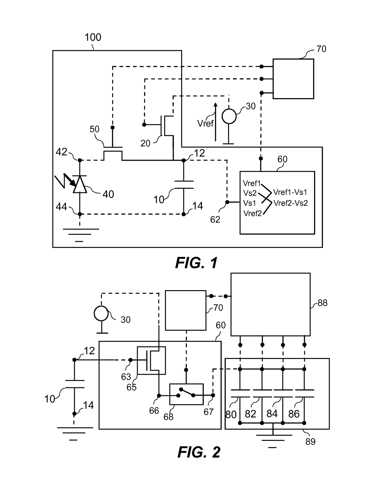
[0028]FIG. 1 schematically shows an example of a pixel circuit 100 and a circuit controller 70 for controlling the pixel circuit 100.

[0029]The pixel circuit 100 comprises a first capacitor 10, a first switch 20, a photo diode 40, a second switch 50, and a sampling circuit 60.

[0030]The first capacitor 10 has a first capacitor terminal 12 and a second capacitor terminal 14. The first capacitor 10 may be a diffusion capacitance, e.g. a n-type diffusion semiconductor region on a p-type semiconductor substrate. A...


PUM


Abstract

A pixel circuit comprises a first capacitor, a photo diode and a switch. A voltage source generates a reference voltage to reset the pixel circuit. The pixel circuit is reset for a first reset time period by electrically coupling a cathode of the photo diode and a first capacitor terminal to the voltage source. The cathode is decoupled from the voltage source and the photo diode is exposed to light for an accumulation time period. After the accumulation time period, a first reference voltage is sampled. The cathode is then coupled, via the switch, to the first capacitor terminal for a selected transfer time period, during which a second signal voltage is sampled. After the selected transfer time period, a first signal voltage is sampled with the cathode decoupled. The pixel circuit is then reset for a second reset time period, after which a second reference voltage value is sampled.

Description

CROSS-REFERENCE TO RELATED APPLICATIONS[0001]This application is the national stage application of and claims priority to International Patent Application No. PCT / EP2014 / 075143 filed on Nov. 20, 2014, the disclosure of which is incorporated by reference herein in its entirety.FIELD OF THE INVENTION[0002]The invention relates to a circuit controller for controlling a pixel circuit, a pixel circuit, an image sensor, a radiation detector and a method of controlling a pixel circuit.BACKGROUND ART[0003]Image sensors are widely used in digital still cameras, security cameras, medical, automobiles, and other applications. Image sensors may work on the basis of pixel circuits. The pixel circuit usually comprises a photo diode and a plurality of transistors. The photo diode collects charges during exposition to light. The plurality of transistors transfers the charges to a bank of capacitors in which the charges are stored as voltages across the capacitors. The voltages are then read by suit...

Claims


Application Information

Patent Timeline
Patent Type & Authority Patents(United States)
IPC IPC(8): H04N5/335H04N5/3745H04N5/357H04N5/374H04N5/378A61B6/00H04N5/355H04N5/217H04N5/363
CPCH04N5/3559A61B6/4208H04N5/3575H04N5/374H04N5/378H04N5/37452H04N5/35536H04N5/363H04N25/59H04N25/616H04N25/65H04N25/771H04N25/58H04N25/75H04N25/76
Inventor MAES, WILLEM HENDRIK
Owner DALSA
Why Eureka
Try Eureka