
Blade positioning

a gas turbine engine and positioning method technology, applied in the direction of machines/engines, liquid fuel engines, manufacturing tools, etc., can solve the problems of reducing engine efficiency, radial gap between the other blade tip and the abradable liner, and affecting the efficiency of engine operation, so as to reduce the leakage of over-tips and improve engine efficiency.

Active Publication Date: 2018-12-25
ROLLS ROYCE PLC
View PDF9 Cites 2 Cited by
  • Summary
  • Abstract
  • Description
  • Claims
  • Application Information

AI Technical Summary

Benefits of technology

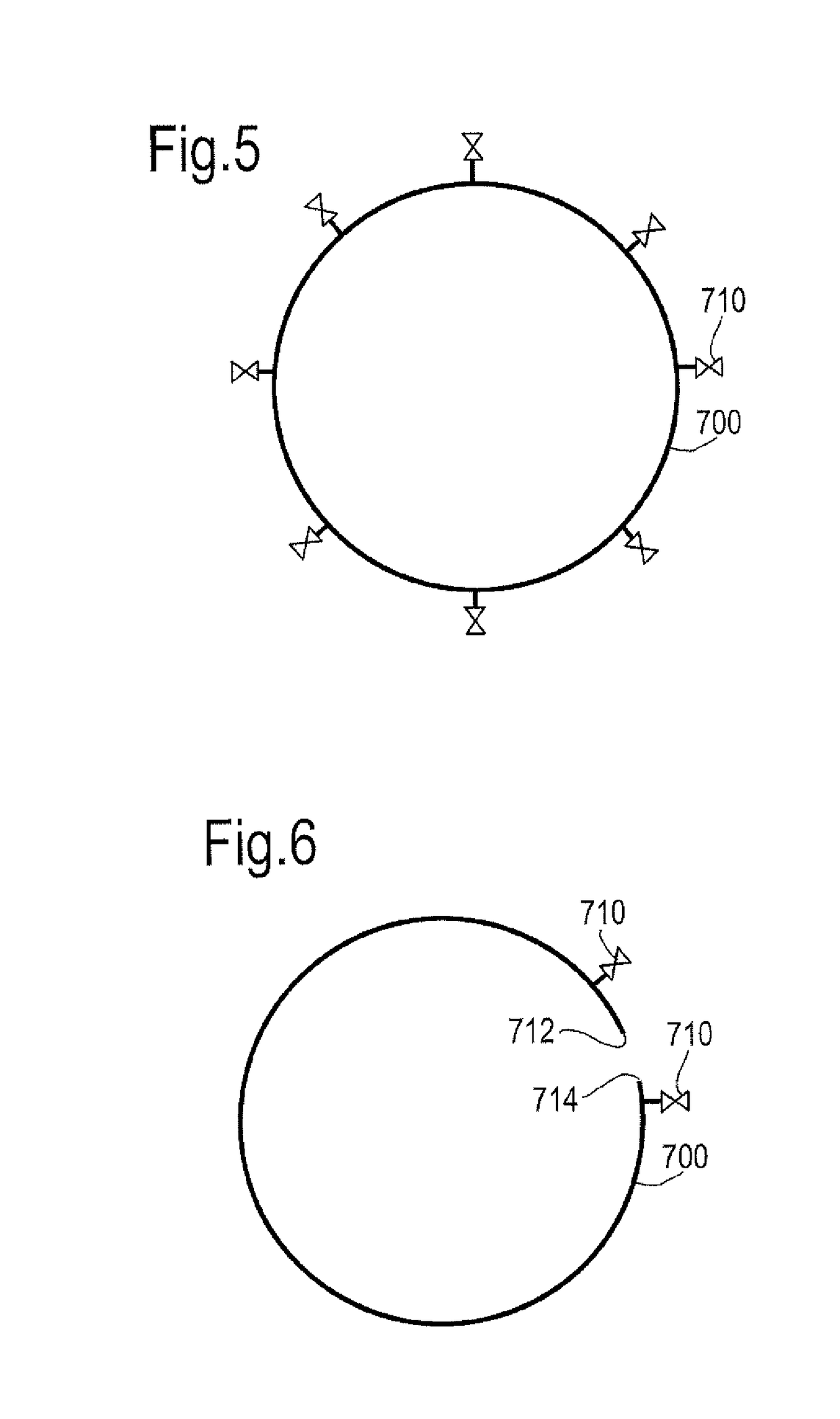
This patent is related to a method and apparatus for grinding the tips of blades used in a wind power machine. The technical effect of the patent is to ensure that the blades are in a known position during use as well as during grinding, which results in blade tips with reduced over-tip leakage and improved engine efficiency. The methods and apparatus may help to ensure that the grinding operation produces blades having uniformly positioned blade tips and more accurate positioning of the blades during the grinding process and / or during use. Additionally, a circumferentially extending fluid-tight bag may be used to prevent circumferential rotation of the blades relative to the slot.

Problems solved by technology

The efficiency at which the engine operates can be affected by flow leaking between the rotor blades and the casing during use, which may be referred to as over-tip leakage.
Any difference in radial tip position means that the abradable liner is abraded away by the blade tip at the further radial position, which in turn results in a radial gap between the other blade tips and the abradable liner.
This radial gap may allow increased over-tip leakage, and thus decreased engine efficiency.
However, a problem occurs during this grinding process which may be said to be because of the way in which the blades are secured into the rotor disc.
When the resulting different shaped and / or sized blades are rotated during running of a gas turbine engine, the differences in their geometry may lead to increased unwanted abrasion of the abradable liner.
In turn, this may result in increased over-tip leakage, and thus decreased stage and engine efficiency.

Method used


Image

  • Blade positioning
  • Blade positioning
  • Blade positioning

Examples


Embodiment Construction

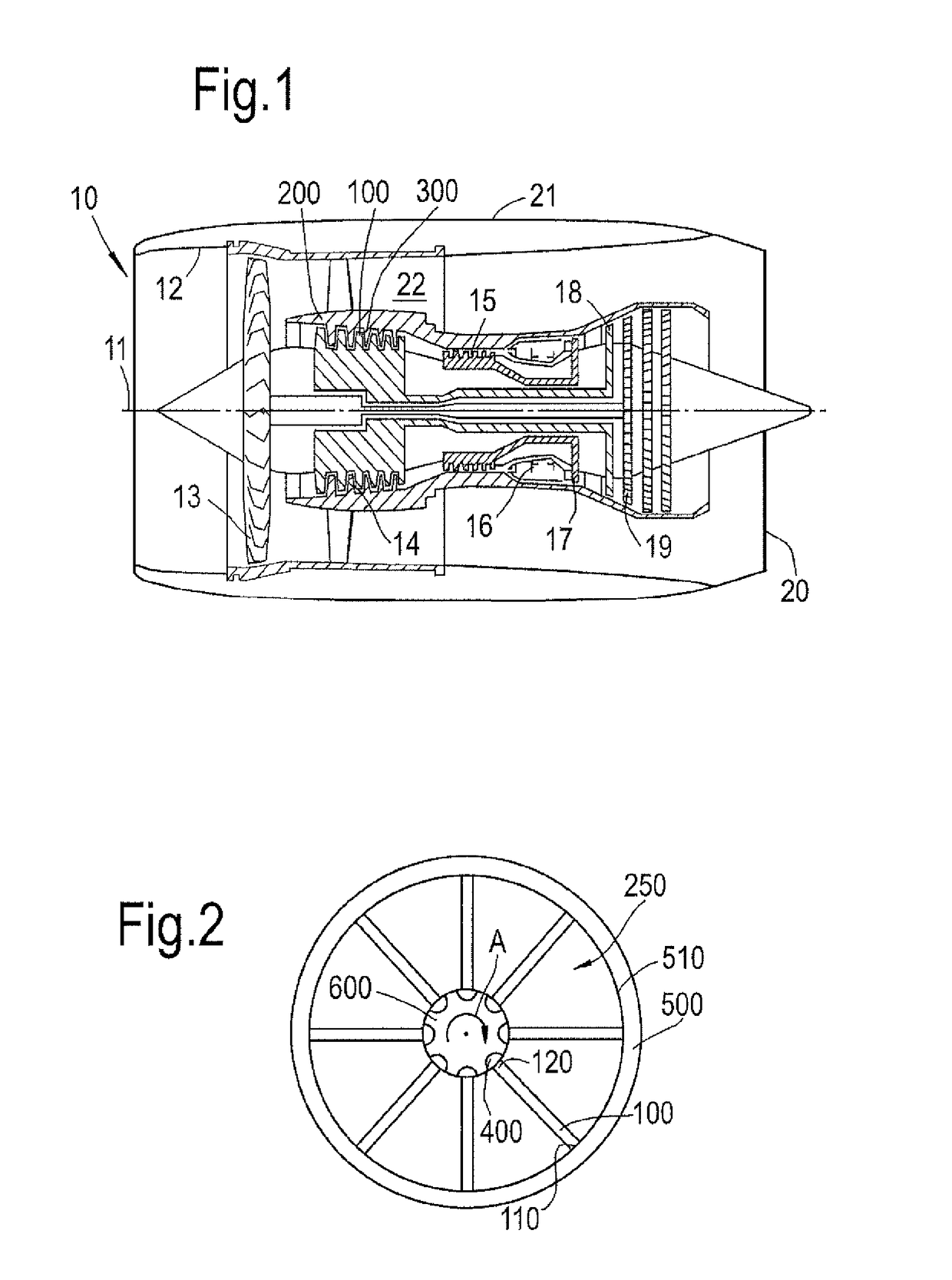
[0048]With reference to FIG. 1, a gas turbine engine is generally indicated at 10, having a principal and rotational axis 11. The engine 10 comprises, in axial flow series, an air intake 12, a propulsive fan 13, an intermediate pressure compressor 14, a high-pressure compressor 15, combustion equipment 16, a high-pressure turbine 17, an intermediate pressure turbine 18, a low-pressure turbine 19 and an exhaust nozzle 20. A nacelle 21 generally surrounds the engine 10 and defines both the intake 12 and the exhaust nozzle 20.

[0049]The gas turbine engine 10 works in the conventional manner so that air entering the intake 12 is accelerated by the fan 13 to produce two air flows: a first air flow into the intermediate pressure compressor 14 and a second air flow which passes through a bypass duct 22 to provide propulsive thrust. The intermediate pressure compressor 14 compresses the air flow directed into it before delivering that air to the high pressure compressor 15 where further comp...


PUM

PropertyMeasurementUnit
pressureaaaaaaaaaa
pressureaaaaaaaaaa
circumferenceaaaaaaaaaa

Abstract

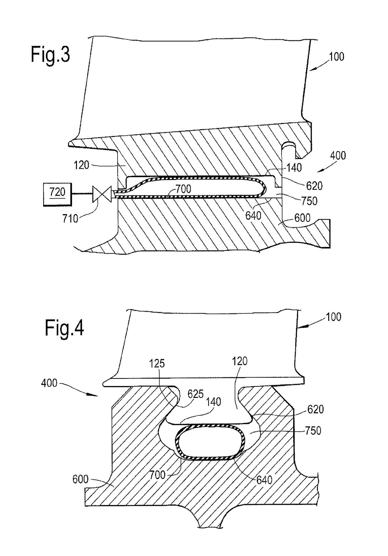
A method of, and apparatus for, urging blades of a gas turbine engine radially outwardly is disclosed. The method may be used to grind blade tips of blades of a rotor stage of a gas turbine engine. The method comprises locating a fluid-tight bag which is in a radial gap formed between a radially inner surface of a respective blade root and a slot in a disc which the blade root cooperates. The method comprises inflating the fluid-tight bag and rotating the rotor stage relative to a grinding surface so as to grind any blade tips that contact the grinding surface during rotation. This results in more accurate positioning of the blades during the grinding process and / or during operation.

Description

CROSS-REFERENCE TO RELATED APPLICATIONS[0001]This application is based upon and claims the benefit of priority from British Patent Application No. 1518570.5 filed 20 Oct. 2015, the entire contents of which are incorporated by reference.BACKGROUND[0002]1. Field of the Disclosure[0003]The present disclosure relates to a method and apparatus for positioning blades of a gas turbine engine, for example during manufacturing the blades of a rotor for a gas turbine engine. In particular, but not exclusively, this invention can relate to a method of grinding the tips of the blades.[0004]2. Description of the Related Art[0005]A gas turbine engine typically comprises multiple rotor stages and multiple stator stages. The rotor stages comprise blades that rotate within a casing. The efficiency at which the engine operates can be affected by flow leaking between the rotor blades and the casing during use, which may be referred to as over-tip leakage. This may apply both to compressor rotor stages...

Claims


Application Information

Patent Timeline
Patent Type & Authority Patents(United States)
IPC IPC(8): B24B19/14B23P15/02F01D5/02F01D5/12F04D29/32F01D11/12F01D25/28F01D5/30
CPCB24B19/14B23P15/02F01D5/02F01D5/12F04D29/324F05D2240/307F01D11/12F01D25/285F05D2220/32F05D2230/10F05D2230/14F01D5/3007
Inventor KEMPF, DANIEL
Owner ROLLS ROYCE PLC
Learn More