Navigation system and method for error correction

a navigation system and error correction technology, applied in the field of error correction, can solve the problems of inability to apply in any situation, inability to find additional measurements at certain points in time, and inconvenient selection of measurement methods, etc., to achieve the effect of improving the selection of measurement used

Active Publication Date: 2019-01-01
HONDA RES INST EUROPE
View PDF22 Cites 1 Cited by
  • Summary
  • Abstract
  • Description
  • Claims
  • Application Information

AI Technical Summary

Benefits of technology

[0012]The new method and navigation system have the advantage that not only an error count is taken into consideration but also the summed up residuals. Thus, the selection of measurements that is further on used in order to calculate correction values is improved because there is the possibility to discard a measurement even in case that the error count is low but the summed up residuals are pretty high. For example if one particular measurement always has residuals when being compared to a redundant measurement that are just below their threshold for increasing the error count summing up these residuals will show significance. Then, with the present invention that uses a combination between the error count and the summed up residuals of a measurement it is possible to discard such measurement nevertheless. Of course, it is also possible to discard a measurement only in case that its error count is above a threshold but to use the summed up residuals for sorting.
[0013]According to an advantageous aspect the error threshold is computed by computing a propagation of the uncertainties of the measurements. This has the advantage that the thresholds themselves are self adaptive. It stabilizes the system, because if for example the base system measurements often contradict the correction measurements, the threshold for accepting a correction measurement is automatically increased. Thus, the discrepancy between redundant measurements needs to be much higher the error count of these measurements is increased and as a consequence the basis for evaluating the combination between the error count and the summed up residuals also changes. This leads to a larger number of correction measurements being taken into consideration.
[0014]According to another preferred embodiment the selection process is performed by repeatedly disregarding the measurement with the greatest summed residual provided that its error count is greater than zero. After discarding one particular measurement with the highest summed residual the identification of redundant measurements, determination of residuals for these redundant measurements, increasing the error count if the residual exceeds a respective threshold, summing up the residuals for each measurement is repeated. The loop is stopped as soon as there is no measurement left the error count of which is greater than zero. The stepwise selection of one measurement to be discarded at a time and thereafter recalculating the values that are the basis for this selection improves the basis for the analysis. Thus, the risk that a measurement is discarded which would in fact be helpful in order to correct a positioning result or the like is reduced.
[0015]According to another advantageous aspect measurements are only discarded if they belong to the correction system. This means that in no case measurements of the base system are discarded. This has the advantage that all the measurements are kept that at least have an analytic redundancy, because these measurements have the highest sampling rate and consequently for each and every measurement there is always at least one (analytic) redundancy to the base system left.
[0016]Keeping all the measurements of the base system results in increasing the error threshold(s) that is computed on the basis of the uncertainties (or the propagation of uncertainties) in case that the base system measurement is often in contradiction with the correction measurements leading to discarding many of the correction measurements. Thus, this leads to stabilizing the system.

Problems solved by technology

Many systems that compute, on the basis of sensor measurements, a desired value or information or estimation, for example movement of objects, encounter significant inaccuracy in the results due to uncertainties in the input values from the sensors as well as processing uncertainties.
This processing can then be combined with additional measurements that are capable of delivering more precise results but the processing of which is for example more time consuming and thus not applicable in any situation.
Furthermore, it might be the case that these additional measurements at certain points in time are not available at all.
But the sensors used in such a system often suffer from errors like for example an offset and also the strapdown algorithm uses internal variables that may cause errors when further processing of the measured values is made.
In addition, such reference measurement may of course also suffer from errors.
In particular, when a GPS system is used, random errors have to be mentioned, for example multipath reception of a satellite signal.
But the computational effort is pretty high.
Furthermore, there is no or very limited possibility of integrating previous knowledge about the measurement set up.
Last but not least, such methods show weaknesses in many different measurements.
These methods show weaknesses if many different measurements shall be cross-evaluated at the same time.
Additionally, the processing load caused by the physical-model-based methods is comparably small which allows efficient processing.
On the other side, it is self-explanatory that such physical-model-based methods necessarily need concrete knowledge about a particular error which limits the usability also.
Finally, in such physical-model-based methods it is difficult to implement stochastic methods so that the two classes as explained above usually are not combined but a particular one is selected in order to satisfy requirements for a specific system.
The problem is that discarding measurement is only determined on the basis of the error count.
Keeping all the measurements of the base system results in increasing the error threshold(s) that is computed on the basis of the uncertainties (or the propagation of uncertainties) in case that the base system measurement is often in contradiction with the correction measurements leading to discarding many of the correction measurements.
Thus, this leads to stabilizing the system.

Method used


Image

  • Navigation system and method for error correction
  • Navigation system and method for error correction

Examples


Embodiment Construction

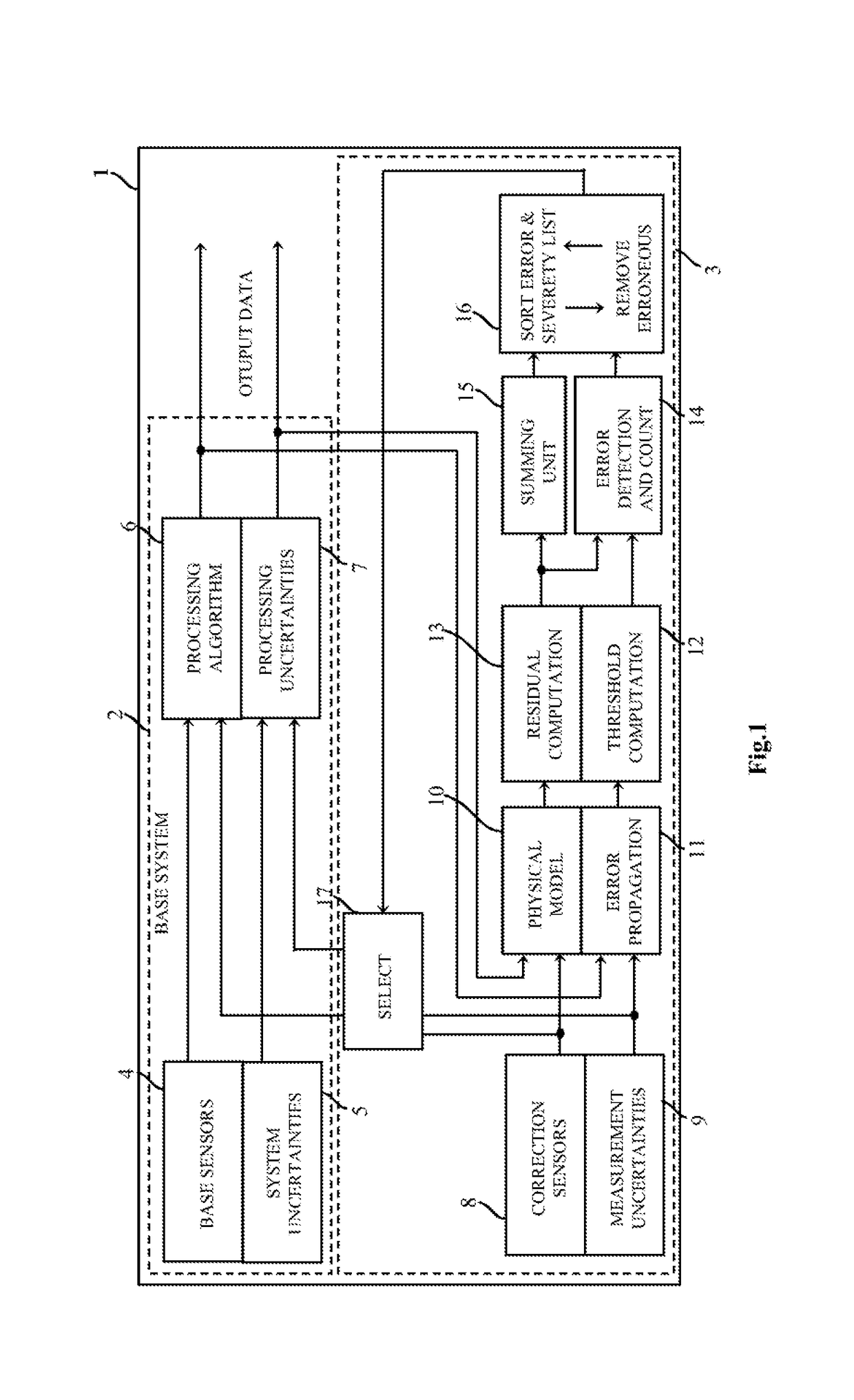
[0023]In FIG. 1 a block diagram is shown which illustrates the main functional blocks of a navigation system 1 which is exemplary for an embodiment of the present invention. The entire navigation system 1 consists of a base system 2 and a correction system 3. The base system 2 comprises base sensors 4 such as three dimensional accelerometers and gyroscopes that measure three dimensional accelerations and angular rates. As indicated with reference numeral 5 base system sensor uncertainties are associated with each of the base sensors 4. Such uncertainties may advantageously be variances and co-variances.

[0024]The raw data that is output by the base sensors 4 is supplied to a processing algorithm unit 6, for example a strapdown algorithm. By the strapdown algorithm and from the base sensor data output data is calculated that comprises for example values for velocity, position and pose. As indicated by the processing uncertainties 7 in addition to the base system sensor uncertainties t...


PUM


Abstract

The invention regards a navigation system and a method for error correction. The navigation system comprises a base navigation system and a correction system. Measurement uncertainties are assigned to each measurement and an error threshold is computed on the basis of these uncertainties. Redundant measurements are determined and residuals for at least a pair of redundant measurements as a discrepancy measure are calculated. In case that the residual exceeds a respective threshold an error count for each measurement involved in the determination of the residual is increased. All residuals for each measurement are summed up for a particular measurement and for carrying out the correction in a fusion filter measurements are selected on the basis of their respective error count and summed up residuals.

Description

BACKGROUNDField[0001]The invention is related to a method for error correction in a system consisting of base system and a correction system, and a navigation system consisting of such base system and correction system.Description of the Related Art[0002]Many systems that compute, on the basis of sensor measurements, a desired value or information or estimation, for example movement of objects, encounter significant inaccuracy in the results due to uncertainties in the input values from the sensors as well as processing uncertainties. In order to correct for those inaccuracies or input errors, it is known to use additional information derived from other sensors as reference measurement. In many cases, it is possible to combine in that way a base system using measurement technique which is easy to handle, always available and easy to process. This processing can then be combined with additional measurements that are capable of delivering more precise results but the processing of whi...

Claims


Application Information

Patent Timeline
Patent Type & Authority Patents(United States)
IPC IPC(8): G01C21/16G01S19/49G01S17/87G01S17/875
CPCG01C21/165G01S19/49G01S17/875G01C21/1652G01C21/188G01C21/1656G01C21/1654
Inventor STEINHARDT, NICO
Owner HONDA RES INST EUROPE
Why Eureka
Try Eureka