
Liquid crystal display detecting system and a method thereof

a detection system and liquid crystal display technology, applied in the field of display drivers, can solve the problems of lcd failure, lcd failure, and the entire lcd, and achieve the effects of increasing the speed of detecting and time to market, enhancing competitiveness, and increasing the speed of manufacturing analysis

Active Publication Date: 2019-01-01
TCL CHINA STAR OPTOELECTRONICS TECH CO LTD
View PDF17 Cites 1 Cited by
  • Summary
  • Abstract
  • Description
  • Claims
  • Application Information

AI Technical Summary

Benefits of technology

[0007]To resolve the aforementioned problem, the present application provides an LCD detecting system and method thereof which avoid a status that entire LCD fails, increase the speed of detecting, and decrease the time of manufacturing analysis.
[0019]The benefit of the present invention is that it increases the speed of detecting and time to market, enhances competitiveness, increases the speed of manufacturing analysis, saves working time and productivity, and reduces cost.

Problems solved by technology

Thus, the conventional mini-low voltage differential signal transmitting between TCON IC and driver IC cannot satisfy the application.
During the detecting or manufacturing process of LCD, if one of driver ICs fails to receive or driver IC is damaged, entire LCD fails because TCON IC continues clock training.
LCD fails so it cannot quickly confirm that TCON IC fails or driver IC fails.
Even it can confirm that driver IC fails but cannot identify the failed driver IC.
Thus, the complication of design is increasing and time for fail manufacturing analysis is increasing.

Method used


Image

  • Liquid crystal display detecting system and a method thereof
  • Liquid crystal display detecting system and a method thereof
  • Liquid crystal display detecting system and a method thereof

Examples


Embodiment Construction

[0028]To better and concisely explain the disclosure, the same name or the same reference number given or appeared in different paragraphs or figures along the specification should has the same or equivalent meanings while it is once defined anywhere of the disclosure.

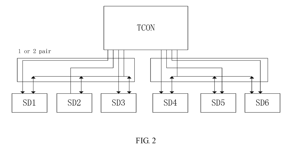
[0029]FIG. 4 is a schematic diagram of a liquid crystal display (LCD) detecting system in accordance with an embodiment of the present invention. The LCD detecting system includes timing control (TCON) IC. The TCON IC includes a process unit to receive lock signal, a detecting control unit connected with the process unit, and a point-to-point transmission unit connected with the detecting control unit.

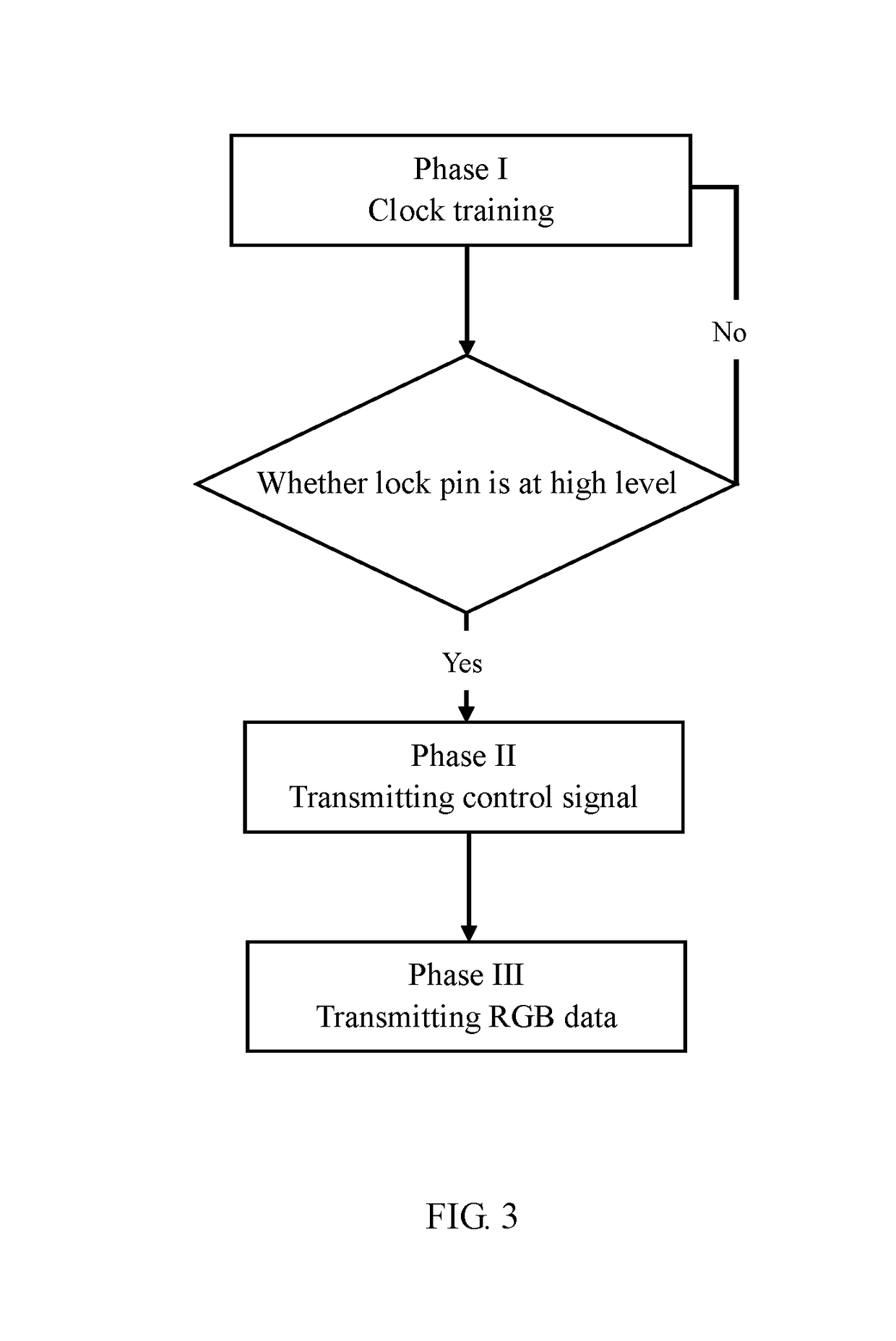
[0030]The detecting control unit detects mode of the point-to-point transmission unit and sends a control signal to the process unit based on a detecting result. The TCON IC transmits timing control signal based on the control signal received by the process unit and starts to transmit normal RGB data. Priority of the cont...


PUM

PropertyMeasurementUnit
timeaaaaaaaaaa
voltageaaaaaaaaaa
clock phaseaaaaaaaaaa

Abstract

The present invention provides an LCD detecting system including timing control (TCON) IC. The TCON IC includes a process unit to receive lock signal, a detecting control unit connected with the process unit, and a point-to-point transmission unit connected with the detecting control unit. The detecting control unit detects mode of the point-to-point transmission unit and sends a control signal to the process unit based on a detecting result. The TCON IC transmits timing control signal based on the control signal received by the process unit and starts to transmit normal RGB data. Priority of the control signal transmitted by the detecting control unit is higher than that of the lock signal. The present invention also provides an LCD detecting method. The present invention can increase the speed of detecting and time to market, enhance competitiveness, increase the speed of manufacturing analysis, saves working time and productivity, and reduces cost.

Description

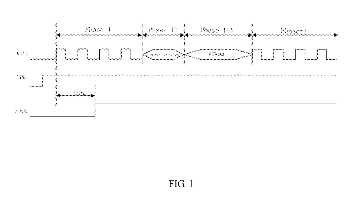
BACKGROUNDTechnical Field[0001]The present invention relates to displaying driver field, and more particularly, to liquid crystal display (LCD) detecting system based on a point-to-point transmission system and a method thereof.Description of Related Art[0002]A liquid crystal display (LCD) panel develops toward high resolution, high refresh rate, and high bits. Data transmitting between timing control (TCON) IC and driver IC is increased tremendously. Thus, the conventional mini-low voltage differential signal transmitting between TCON IC and driver IC cannot satisfy the application.[0003]In the conventional art, high efficiency data signal is adopted to solve the conventional problem of catching wrong signal resulted from clock phase difference produced by separating clock signal and data signal. Adopting built-in clock signal usually can avoid phase difference and high efficiency data signal is usually transmitted point to point. Adopting built-in clock signal needs to transmit cl...

Claims


Application Information

Patent Timeline
Patent Type & Authority Patents(United States)
IPC IPC(8): G06F1/00G09G5/18G02F1/133G09G3/36G09G3/00G09G5/00G09G3/20G09G1/00
CPCG02F1/133G09G3/00G09G3/2096G09G3/36G09G5/006G09G5/18G09G2370/08G05B2219/00G06F2101/00G09G1/00G09G2310/0264G09G2310/08G09G3/006G09G5/008
Inventor XIONG, ZHI
Owner TCL CHINA STAR OPTOELECTRONICS TECH CO LTD
Learn More