Power line fault locating system

a fault locating and power line technology, applied in the direction of fault location by conductor type, measurement using digital techniques, instruments, etc., can solve the problems of power outages, noise on the power line is not detected, and the installation of the system is easy and safer

Active Publication Date: 2019-01-08
REILLEY PETER
View PDF21 Cites 5 Cited by
  • Summary
  • Abstract
  • Description
  • Claims
  • Application Information

AI Technical Summary

Benefits of technology

[0033]The Noise Source Locating System has significant advantages over the existing systems. It is able to locate an arcing fault without having detectors connected to the power lines; rather the system receives the radiated electromagnetic emissions through the air. The location is found by correlating the data received from multiple detectors. The correlation data along with precise timing data provides the physical distance to the fault. The data is not expected to have any recognizable patte

Problems solved by technology

Power outages can result from many different causes, some internal to the system such as equipment failure others from external causes such as a tree falling on a power line.
Often the problem is quickly locating the point of failure.
Some types of faults such as noise on the power lines are not detected by these devices.
Such noise can emanate from arcing around mounting bolts and fixtures.
However, noise often indicates a fault with the equipment and can result in an eventual failure.
This noise, even if it is not a problem for the utility, can be a problem for other people in the area.
It can disrupt radio communication, television reception, and other equipment.
Above certain limits this noise can violate government restrictions on unintended radiation emissions.
This can result in fines.
This is tedious, time consuming, and

Method used


Image

  • Power line fault locating system
  • Power line fault locating system
  • Power line fault locating system

Examples


Embodiment Construction

—LIST OF DRAWING ELEMENTS

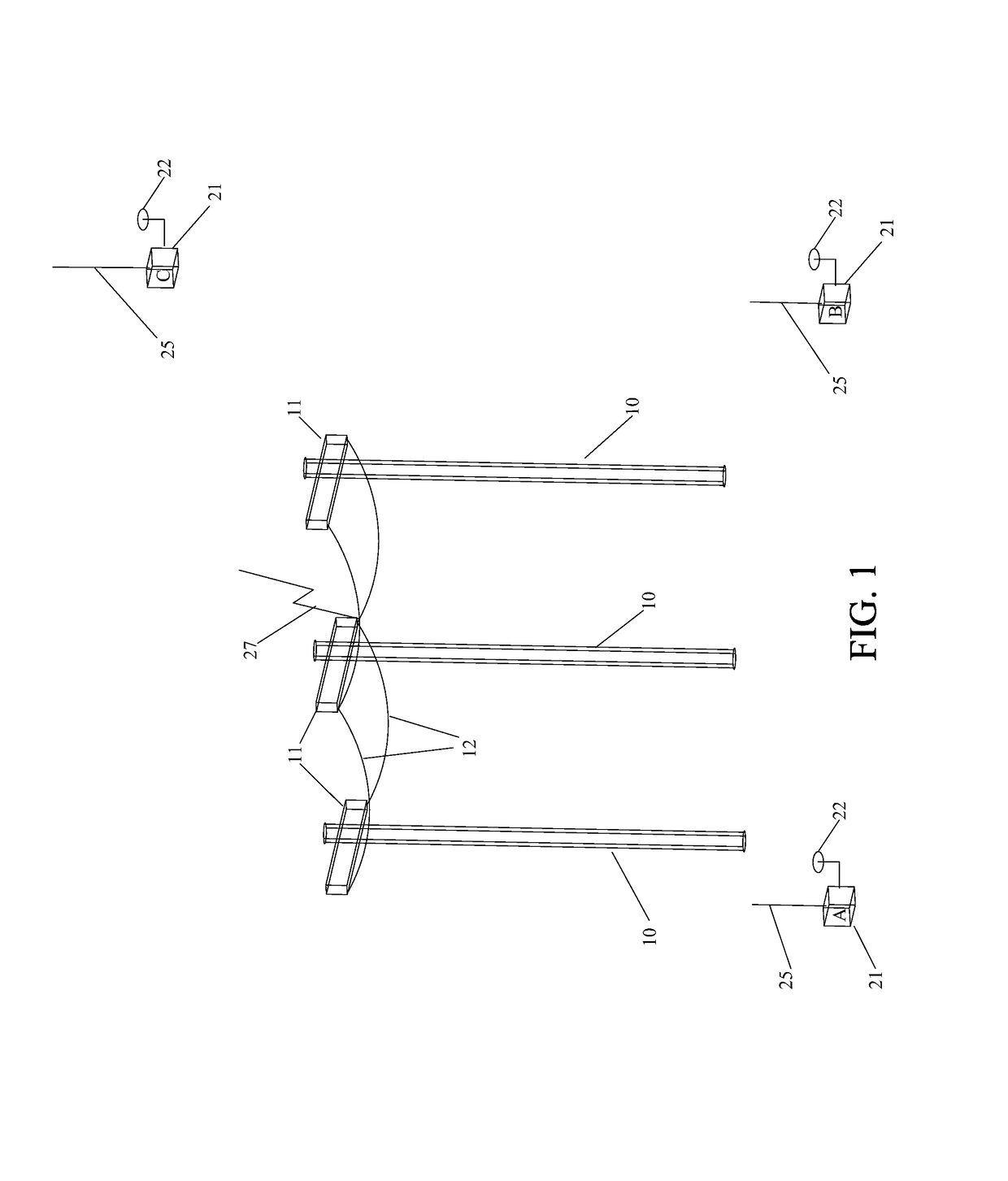
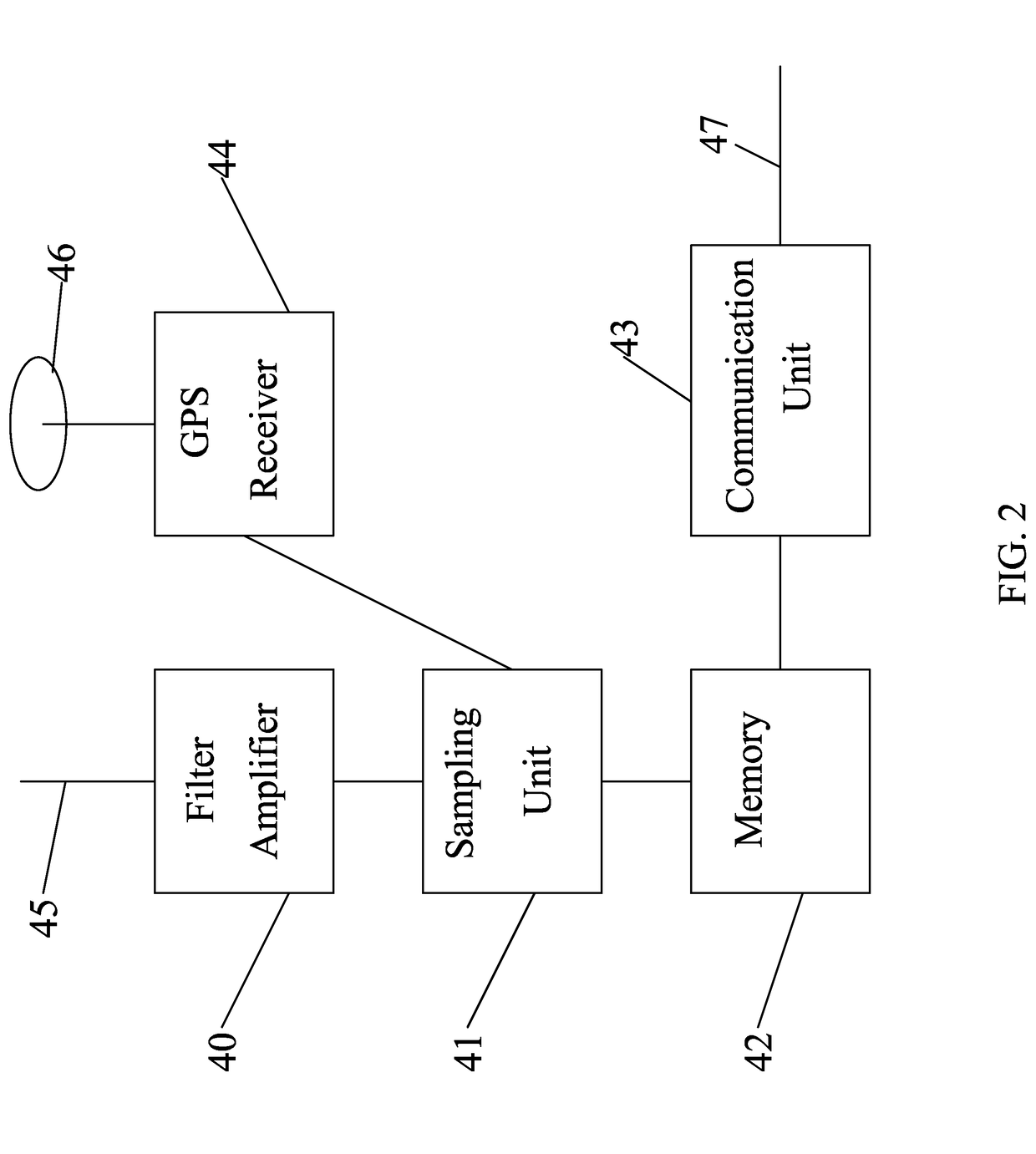
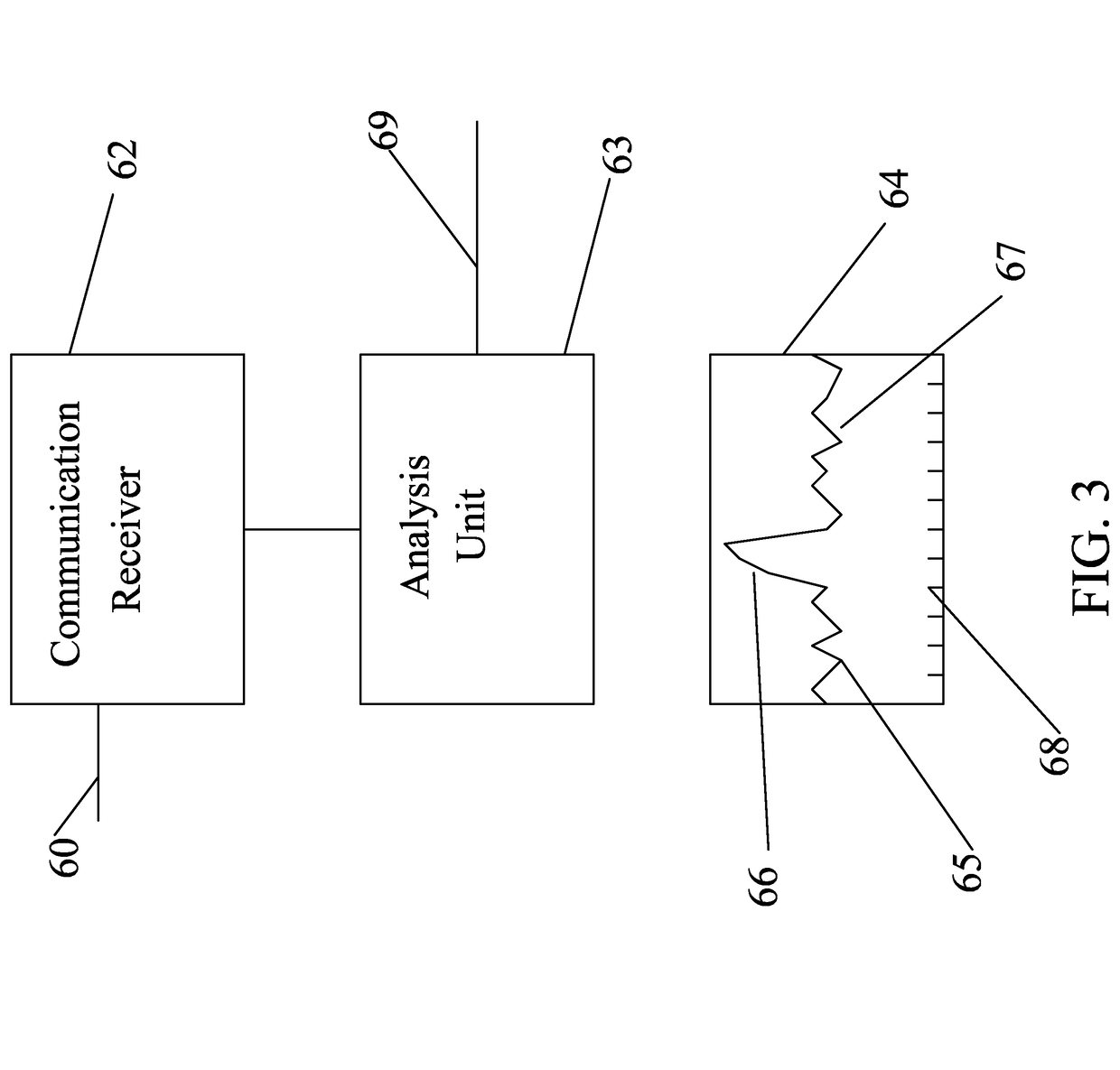
[0042]10. Utility poles[0043]11. Utility pole cross members.[0044]12. Power lines.[0045]21. Receiving units.[0046]22. GPS antennas.[0047]25. Receiving antennas.[0048]27. Location of fault.[0049]40. Filter / amplifier.[0050]41. Sampling unit.[0051]42. Memory.[0052]43. Communication unit.[0053]44. Global Positioning System (GPS) receiver.[0054]45. Receiving antenna.[0055]46. GPS antenna.[0056]47. Outgoing communication link.[0057]60. Incoming data from the monitoring units.[0058]62. Communication receiver.[0059]63. Analysis Unit.[0060]64. Plot of correlation results.[0061]65. Correlation background noise.[0062]66. Correlation peek.[0063]67. Correlation graph.[0064]68. Distance scale.[0065]69. Communication channel for correlation data.[0066]80. Heatmap summing unit.[0067]81. Communication channel to receive correlation data.[0068]82. Heatmap result.[0069]83. Heatmap data for users.[0070]85. Heatmap graph showing utility poles.[0071]86. Latitude scale of graph.[0...


PUM


Abstract

The Power Line Fault Locating System is a means of locating faults in a utility power system by sampling the noise at multiple positions around the system and correlating and summing the resulting data. When the processed data produces a spike, a noise source has been detected. The position of the spike in the data will indicate the location of the noise source with great precision. With three of more receivers the location of the fault can be determined in two dimensions. The invention can operate on both continuous noise resulting from minor flaws in the power system as well as the noise burst resulting from a power system failure. Noise resulting from minor flaws may come from slack line fittings, electrical leakage in insulators or at poles. A burst of noise may come from insulator flash over, lightning strike, or something contacting a power line.

Description

CROSS-REFERENCE TO RELATED APPLICATIONS[0001]This application is a continuation in part (CIP) of application Ser. No. 13 / 594,807 filed on Aug. 25, 2012 which is hereby incorporated for all purposes.CROSS-REFERENCE TO RELATED APPLICATIONS[0002]Not ApplicableFEDERALLY SPONSORED RESEARCH[0003]Not ApplicableSEQUENCE LISTING OR PROGRAM[0004]Not ApplicableBACKGROUND OF THE INVENTION[0005]Field of Invention[0006]This invention relates to finding the location of a fault on a power line.[0007]Prior Art[0008]Electric utilities must monitor their transmission lines to insure their proper operation and prevent damage to their systems or customers equipment. Power outages can result from many different causes, some internal to the system such as equipment failure others from external causes such as a tree falling on a power line. In all cases the utility must find and repair the damage as rapidly as possible. Often the problem is quickly locating the point of failure. Utilities use many differen...

Claims


Application Information

Patent Timeline
IPC IPC(8): G01R31/08G01R31/00G01R31/02G01R31/28H02H1/00G01R19/25G01R31/50
CPCG01R31/088G01R31/085G01R31/001G01R31/02G01R31/281Y04S10/522G01R31/08G01R19/2513H02H1/0015G01R31/50Y04S10/52
Inventor REILLEY, PETER
Owner REILLEY PETER
Why Eureka
Try Eureka