Moving-vane angle of attack probe

a technology of moving vane and probe, which is applied in the direction of stators, machines/engines, instruments, etc., can solve the problems of large de-icing power, and a large surface area of integrated sensors, so as to reduce de-icing power, reduce surface area, and efficient feature arrangement

Inactive Publication Date: 2019-01-15
MEGGIT (UK) LTD
View PDF21 Cites 3 Cited by
  • Summary
  • Abstract
  • Description
  • Claims
  • Application Information

AI Technical Summary

Benefits of technology

[0007]The present inventor has identified that a reduction in the de-icing power required by a multi-sensor probe may be achieved by reducing the total surface area of the probe. The inventor then recognised that, for angle of attack and total pressure sensing probe, this could be achieved by positioning a pitot-tube, which requires significant de-icing power, inside the body of a moving-vane. The present inventor also identified that this further contributed to reducing the required de-icing power as the heat that radiates outwards as the pitot-tube is de-iced can now be used to de-ice the surrounding vane.
[0037]In these embodiments, the moving vane angle of attack probe provides angle of attack measurements and static pressure measurements. These embodiments also provide the same benefits of reduced de-icing power as the first aspect by allowing for a reduced surface area and efficient arrangement of features. These embodiments further include at least one pressure system which has a static pressure defect corrected by a shaped vane surface. Specifically, the correction is performed by positioning the static pressure port in a depression in the surface of the vane, as described above with respect to the first aspect.

Problems solved by technology

This results in a fairly complex installation, with each sensor requiring power, data communications and in the case of pitot-static systems, pneumatic connections.
In both these cases, the integrated sensors have a large surface area and require significant de-icing power to maintain functionality of the probe.
An alternative approach has been to add additional pressure ports to a conventional pitot-static probe and use differential pressure measurements to calculate angle of attack, as described in U.S. Pat. No. 4,378,696 A. These probes also require considerable de-icing power and additionally have the disadvantage that the angle of attack measurements are not independent of the pitot-static pressure measurements, which could result in a common mode failure affecting both the air data system and the stall warning system.

Method used


Image

  • Moving-vane angle of attack probe
  • Moving-vane angle of attack probe
  • Moving-vane angle of attack probe

Examples


first embodiment

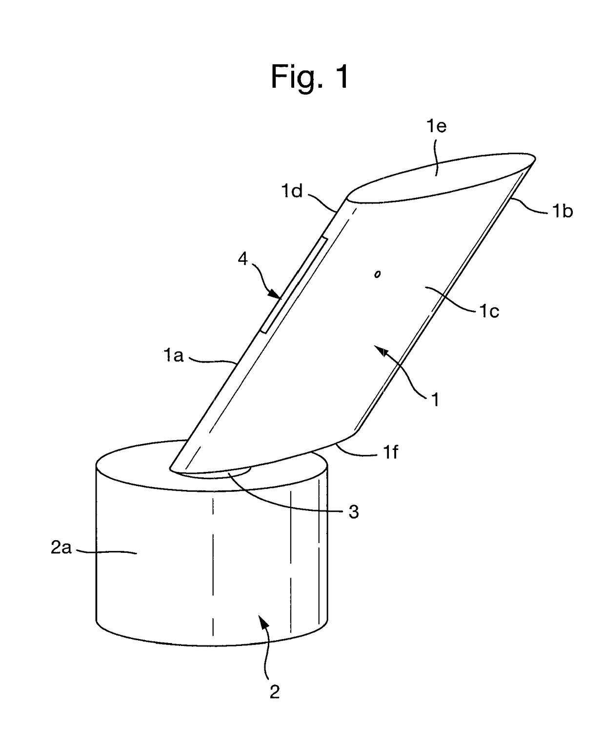
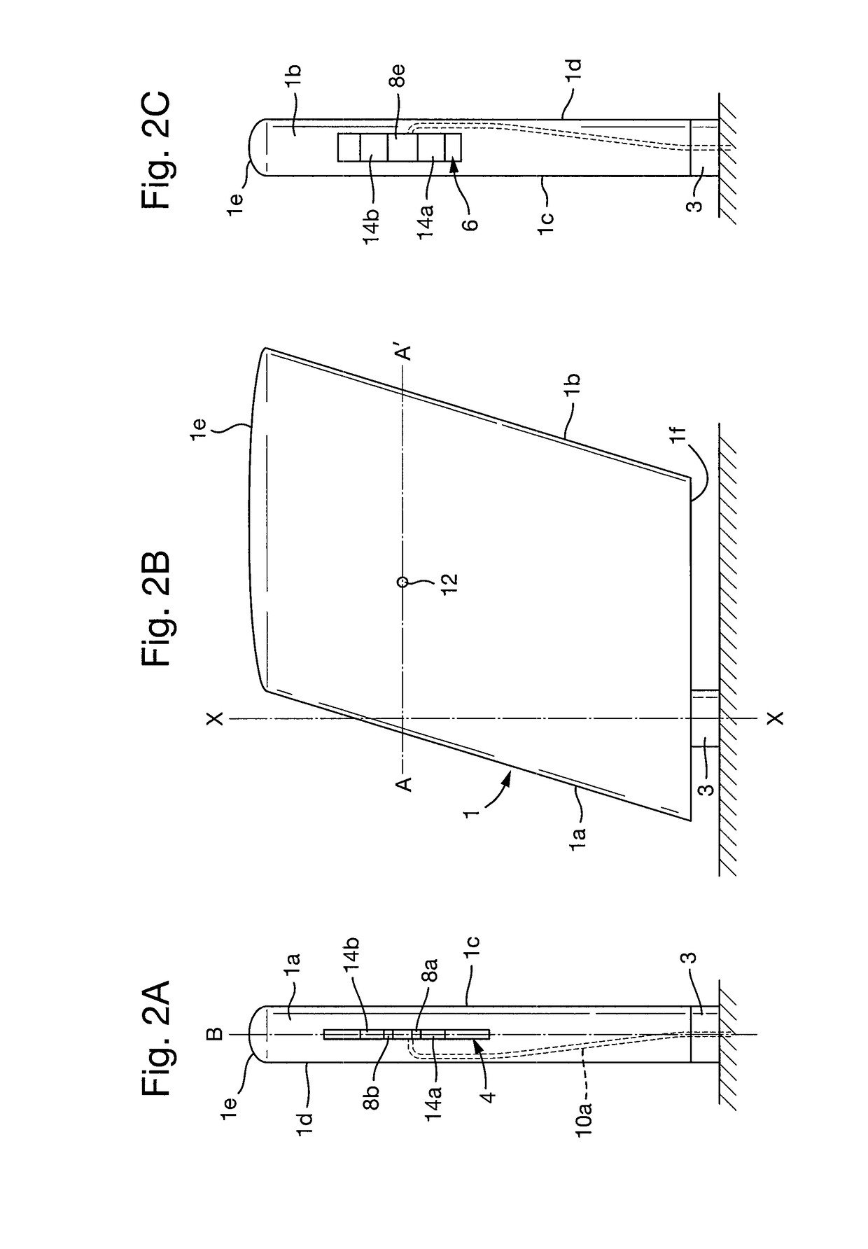
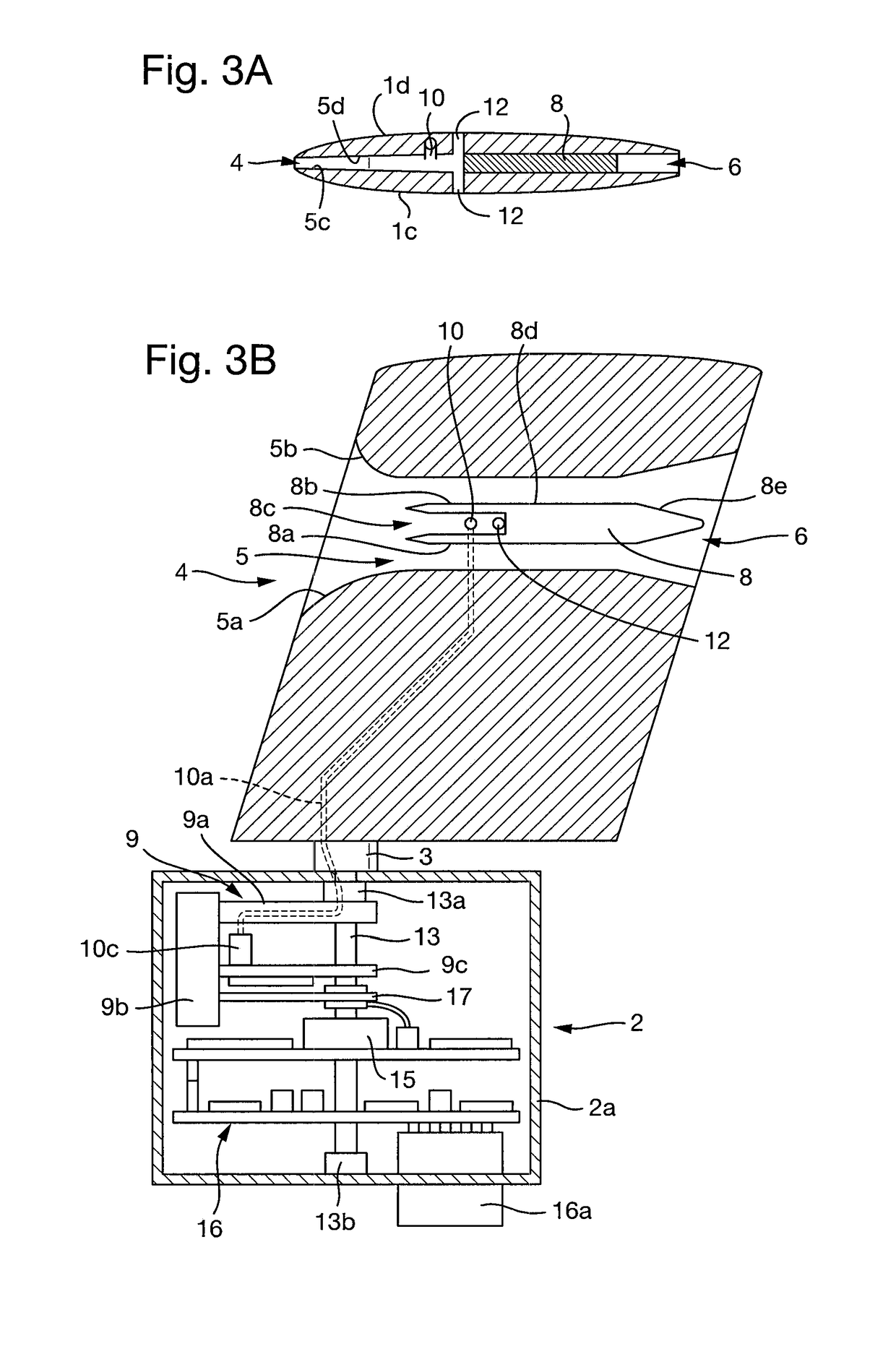
[0092]The first embodiment represents an integrated sensor for determining both the angle of attack, based on the rotational position of the vane, and the total pressure, based on the air pressure in the pitot-tube 8. While it is advantageous to integrate these two sensors into a single assembly, in order to calculate, for example, the Mach number, the static pressure as well as the total pressure must be known. It is therefore particularly advantageous for the moving-vane angle of attack probe to further include static pressure sensors.

[0093]The second embodiment of the invention, shown in FIGS. 4 to 7B, will now be described. The embodiment of FIGS. 4 to 7B is largely the same as the embodiment of FIGS. 1 to 3B, and the same reference numerals for identical features will be adhered to. The moving-vane angle of attack probe of this embodiment differs in that a pitot-static system is incorporated into the vane rather than a pitot-tube. The pitot-static tube is largely the same as th...

second embodiment

[0094]The static pressure systems are ideally to be used to determine the freestream pressure, which is the air pressure upstream of the vane, i.e. before the air pressure has been affected by the movement of an aerodynamic body. However, in reality the static pressure in the region of the vane will be affected by a number of factors. Firstly, the static pressure in the region of the vane will be affected by the movement of the body on which the vane is mounted, for example, the fuselage of a plane. Secondly, the static pressure in the region of the vane will be affected by the way in which the air flows over the vane itself. Finally, the static pressure in the region of the vane will be affected in a scenario in which the angle of the vane lags behind a change in wind direction. As described below, the invention features a number of design considerations made to minimise or correct for these effects on the static pressure.

[0095]The first and second static pressure systems 81, 82 co...

third embodiment

[0104]In the invention, a vane is provided with the first and second static pressure systems only, as shown in FIGS. 8 to 10B.

[0105]In this embodiment, the vane is of substantially the same external shape as in the first two embodiments, but does not have an opening, interior chamber, or exhaust opening. In this embodiment, the first and second static pressure systems 281, 282 comprise first and second manifolds 281c, 282c respectively. The first and second manifolds are cuboidal chambers located inside the vane.

[0106]Each static pressure system 281, 282 further comprises a pair of static ports 281a, 281b, 282a, 282b. The first static pressure system 281 features a first static port 281a, which extends from the first vane surface 1c, through the vane to the first manifold, thereby connecting it to the atmosphere. The first static pressure system 281 further features a second static pressure port 281b which extends from the second vane surface 1d, through the vane to the first manifo...


PUM


Abstract

A moving-vane angle of attack probe is provided. The moving-vane angle of attack probe comprises: a vane having opposed first and second vane surfaces that define a leading edge and a trailing edge, the first and second vane surfaces, each extending between the leading edge and the trailing edge; a first vane opening located on the leading edge; at least one exhaust opening; a vane conduit extending between the first vane opening and the exhaust opening such that the first vane opening and the exhaust opening are in fluid communication, the vane conduit defining at least an interior chamber between the first and second vane surfaces; and a pitot-tube located within the interior chamber such that in use it receives air that enters the interior chamber via the first vane opening.

Description

FIELD OF THE INVENTION[0001]The present invention is directed to a moving-vane angle of attack probe.DESCRIPTION OF THE RELATED ART[0002]Conventionally, aircraft have been fitted with separate air data sensors for measuring pitot-static pressure, angle of attack and temperature. This results in a fairly complex installation, with each sensor requiring power, data communications and in the case of pitot-static systems, pneumatic connections. To reduce system complexity, multi-function probes have been produced which perform the functions of two or more of these sensors, usually with integral measurement and processing capability.[0003]In particular, moving-vane angle of attack probes have been integrated with pitot-static pressure sensors by mounting a conventional pitot-tube on the top of a moving vane. Examples of such probes may be found in U.S. Pat. No. 4,672,846 A, U.S. Pat. No. 6,679,112 BB, U.S. Pat. No. 6,817,240 BB, and U.S. Pat. No. 7,155,968 BB. Alternatively, probes with ...

Claims


Application Information

Patent Timeline
Patent Type & Authority Patents(United States)
IPC IPC(8): G01P5/06G01P13/02F01D21/00G01P5/165F01D9/02
CPCF01D21/003F01D9/02G01P13/025G01P5/165G01P5/06G01P13/004
Inventor WADDINGTON, ALAN
Owner MEGGIT (UK) LTD
Why Eureka
Try Eureka