
Treatment of skeletal voids with implantable substrate hydrated with bone marrow concentrate

a technology of bone marrow concentrate and implantable substrate, which is applied in the field of medical devices and procedures, can solve the problems of bone substitutes, impractical use, pain and local donor site morbidity, etc., and achieve the effects of maximizing the regenerative capacity of implants, minimizing the implantation space, and promoting bone healing

Active Publication Date: 2019-01-22
SPINESMITH PARTNERS
View PDF4 Cites 0 Cited by
  • Summary
  • Abstract
  • Description
  • Claims
  • Application Information

AI Technical Summary

Benefits of technology

This patent text discusses the use of a moldable scaffolding material, called hydroxyapatite, which can be formed to fit irregular defects in bones and promote bone growth. The scaffold is combined with concentrated autologous cells, which are known to support bone healing, and delivered directly to the site of injury. This method minimizes the implantation space and maximizes the regenerative capabilities of the implant, making it effective for any defect within the body, including spine, pelvis, and extremities.

Problems solved by technology

Autografts, considered the gold standard in bone substitutes, are impractical for use in larger defects as graft size would be limited to patient sample availability.
Additionally, pain as well as local donor site morbidity are commonly reported at the site of graft harvesting.
In clinical application, this type of scaffold would be impractical.
An implanted scaffold would need to fill the entire volume of the defect, but having a pre-formed scaffold would limit its application to defects of specific sizes or require the physician to modify the graft or the graft site.
This modification could have deleterious effects to the patient in that use of a reamer or burr to change the defect site can cause heat generation potentially resulting in local tissue necrosis.
This approach has been validated in limited studies without specific tailoring of granule porosity or surface area nor thorough characterization of the cellular component of the graft.

Method used


Image

  • Treatment of skeletal voids with implantable substrate hydrated with bone marrow concentrate
  • Treatment of skeletal voids with implantable substrate hydrated with bone marrow concentrate
  • Treatment of skeletal voids with implantable substrate hydrated with bone marrow concentrate

Examples


Embodiment Construction

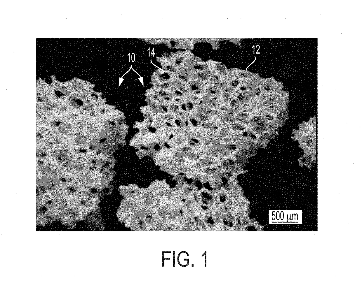
[0026]The extracellular matrix of hard tissues is composed of two distinct phases, an organic phase and an inorganic phase. The inorganic portion of bone is comprised mainly of hydroxyapatite while the organic phase is primarily comprised of type I collagen and smaller amounts of other proteins. Structurally, although hard, bone is a porous material, with porosities of 50-90% in trabecular bone and 3-12% in cortical bone. By providing a substrate containing osteogenic progenitor cells, in combination with the biological binding cues from the organic phase as well as some of the mechanical rigidity seen in the inorganic phase, it may be possible to produce a fully functional device capable of supporting osteogenic differentiation as well as new bone growth. In certain embodiments, the organic phase contains growth factors and / or proteins that aid in the repair process.

[0027]Calcium phosphate based materials are a popular synthetic bone graft material because they have been shown to d...


PUM

PropertyMeasurementUnit
porosityaaaaaaaaaa
porosityaaaaaaaaaa
porositiesaaaaaaaaaa

Abstract

The invention is directed to a bone void filler comprising a scaffold or matrix. The scaffold or matrix may include a porous inorganic matrix component. The bone void filler may include a cellular component containing cells, some of which are capable of making extracellular matrix resembling native bone tissue. The bone void filler may include an organic matrix, such as, an organic biopolymer that aids in cell retention and renders the scaffold or matrix moldable. The bone void filler may include growth factors and / or cytokines. The bone void filler may include a clotting agent.

Description

CROSS-REFERENCES TO RELATED APPLICATIONS[0001]This application claims the benefit under 35 U.S.C. § 119(e) of U.S. Provisional Patent Application No. 62 / 067,815 filed Oct. 23, 2014, which is incorporated herein by reference in its entirety as if fully set forth herein.BACKGROUND OF THE INVENTION[0002]The claimed invention relates generally to medical devices and procedures and more particularly to devices and methods for treating defects in the tissue of a living being.[0003]To better treat our aging population, physicians are looking for new and better products and methods to enhance the body's own mechanism to produce rapid healing of musculoskeletal injuries and degenerative diseases. Treatment of these defects has traditionally relied upon the natural ability of these types of tissue to repair themselves. In many instances the body is unable to repair such defects in a reasonable time, if at all. Advances in biomaterials has allowed for the creation of devices to facilitate woun...

Claims


Application Information

Patent Timeline
Patent Type & Authority Patents(United States)
IPC IPC(8): A61L27/22A61L27/38A61L27/24A61L27/56A61L27/20A61L27/12
CPCA61L27/12A61L27/20A61L27/22A61L27/222A61L27/225A61L27/24A61L27/3834A61L27/3847A61L27/56A61L27/227A61L2430/02
Inventor DAWSON, EILEENDUNWORTH, KEVINSAND, THEODOREMURPHY, MATTHEWROSSMAN, JOHN B.SAMANO, MELISSASUZUKI, RICHARDMONCIVAIS, KATY
Owner SPINESMITH PARTNERS
Learn More