
Radiofrequency ablation catheter with optical tissue evaluation

a radiofrequency ablation and optical tissue technology, applied in the direction of diagnostics using light, surgical instruments for heating, surgical instruments for irrigation of substances, etc., can solve the problems of inability to accurately identify the complete necrosis with current tools, difficulty in consistent results, and limited effectiveness of procedures, so as to achieve the effect of improving the effect of atrial fibrillation

Active Publication Date: 2019-02-05
MEDLUMICS
View PDF43 Cites 21 Cited by
  • Summary
  • Abstract
  • Description
  • Claims
  • Application Information

AI Technical Summary

Benefits of technology

The patent describes a way to improve the process of ablating tissue in the heart to treat atrial fibrillation. This is done by monitoring the procedure in real-time using a special technique called low coherence interferometry (LCI). This helps to ensure that the ablation is effective and can improve the overall success of the treatment.

Problems solved by technology

Because of the variability of these parameters, it is difficult to obtain consistent results.
Indeed, this procedure has shown only limited effectiveness when used in atrial fibrillation, with individual success rates strongly dependent on the expertise and ability of the clinician performing it.
Incomplete ablation resulting in edema rather than complete necrosis cannot be properly identified with current tools.
One further problem with catheter ablation is the long intervention times that are required in point-to-point procedures in the atrium.
Ensuring the continuity of such a pattern in a beating heart requires painstaking work and attention.
Since the procedure is often performed with the support of fluoroscopy, it can pose a significant radiation dose to the clinician and the patient.

Method used


Image

  • Radiofrequency ablation catheter with optical tissue evaluation
  • Radiofrequency ablation catheter with optical tissue evaluation
  • Radiofrequency ablation catheter with optical tissue evaluation

Examples


Embodiment Construction

[0027]Although specific configurations and arrangements are discussed, it should be understood that this is done for illustrative purposes only. A person skilled in the pertinent art will recognize that other configurations and arrangements can be used without departing from the spirit and scope of the present invention. It will be apparent to a person skilled in the pertinent art that this invention can also be employed in a variety of other applications.

[0028]It is noted that references in the specification to “one embodiment,”“an embodiment,”“an example embodiment,” etc., indicate that the embodiment described may include a particular feature, structure, or characteristic, but every embodiment may not necessarily include the particular feature, structure, or characteristic. Moreover, such phrases do not necessarily refer to the same embodiment. Further, when a particular feature, structure or characteristic is described in connection with an embodiment, it would be within the kno...


PUM


Abstract

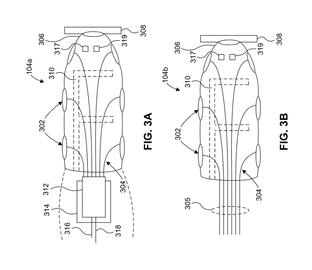
Systems and methods for performing RF ablation while monitoring the procedure using low coherence interferometry (LCI) data are described. A catheter includes a distal section, a proximal section, a multiplexer, and a sheath coupled between the distal section and the proximal section. The distal section includes several interconnected optical ports configured to transmit exposure radiation toward a sample and receive radiation that have been reflected or scattered from the sample. The interconnected optical ports are formed on a substrate having rigid sections and flexible sections arranged around the distal section. A holder maintains the interconnected optical elements in a fixed spatial relationship.

Description

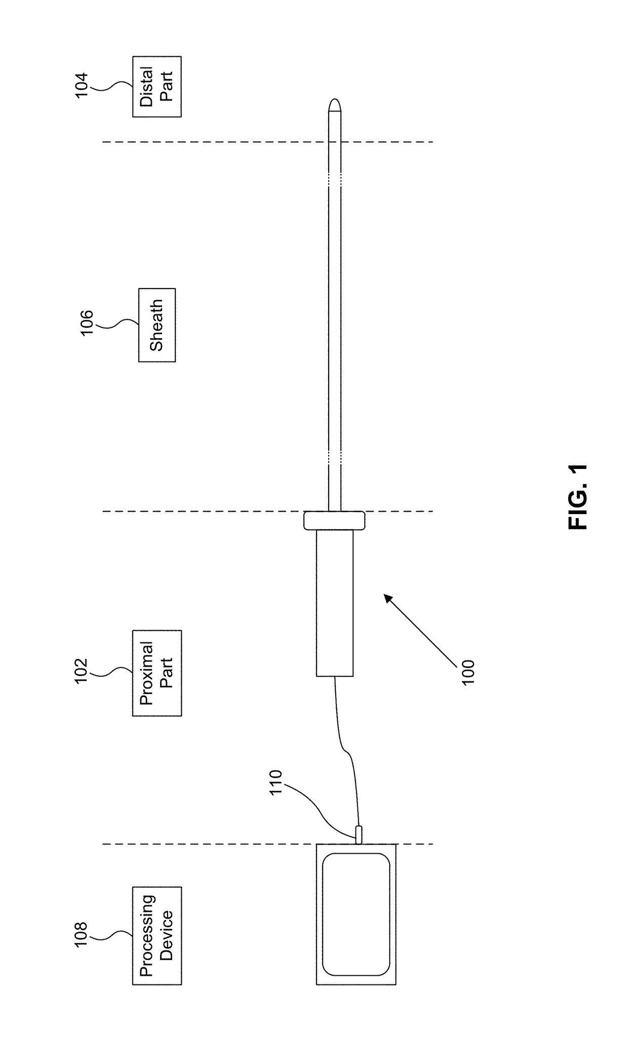
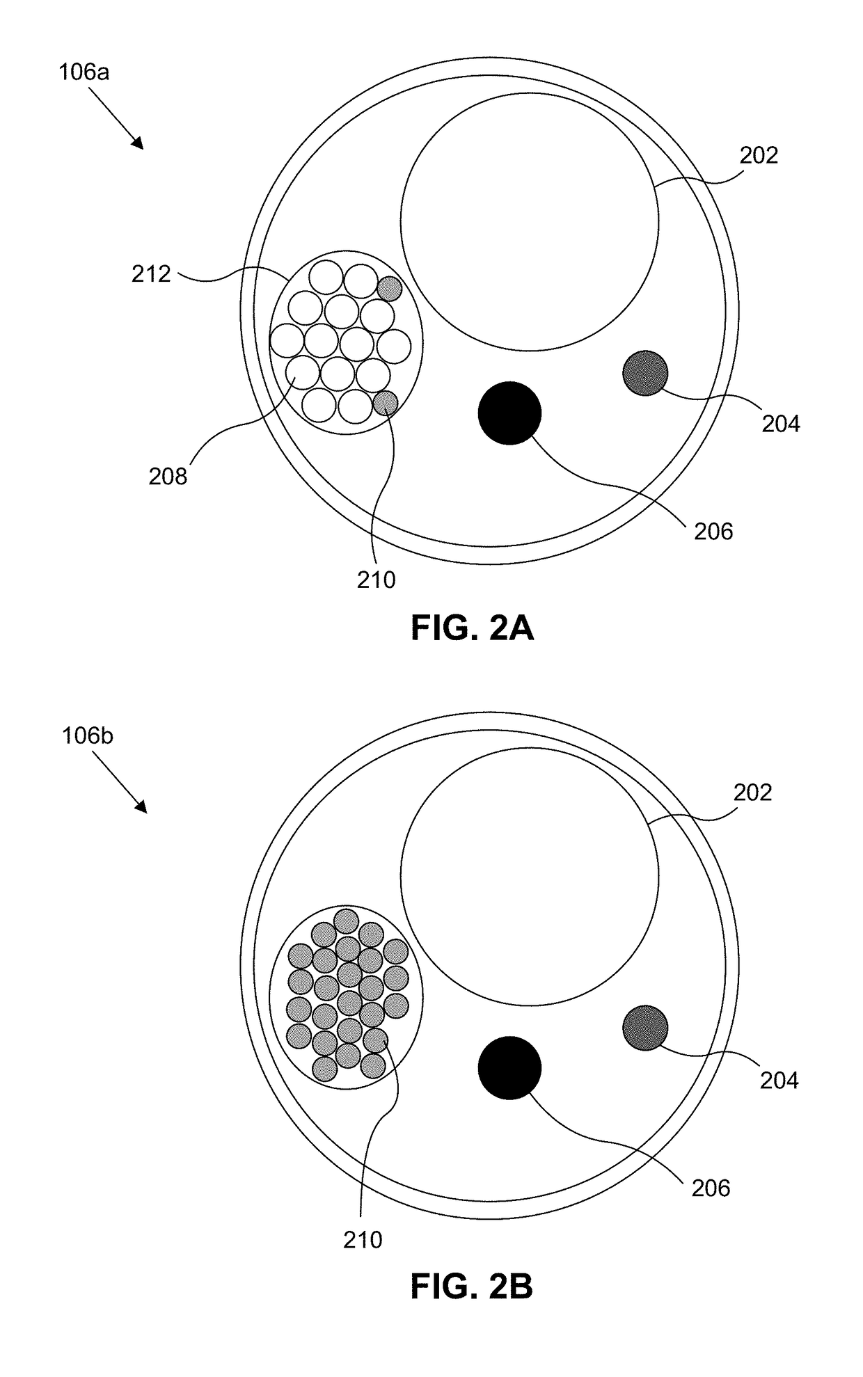
[0001]This application claims priority to application Ser. No. 62 / 198,591 filed Jul. 29, 2015, which is hereby incorporated by reference in its entirety.BACKGROUND[0002]Field[0003]Embodiments of the invention relate to designs of, and methods of using, an RF ablation catheter together with optical tissue inspection.[0004]Background[0005]Radiofrequency (RF) ablation is a medical technique to produce tissue necrosis. It is used to help treat different pathologies including cancer, Barret's esophagus, or cardiac arrhythmias, among others. The application of alternating current with an oscillating frequency above several hundreds of kHz avoids the stimulation of excitable tissue while delivering heat by means of the Joule's effect. The increase in tissue temperature produces denaturation of the biological molecules, including proteins such as collagen. Traditionally, RF ablation is done by placing an external electrode on the patient's body, and applying an alternating potential to the ...

Claims


Application Information

Patent Timeline
Patent Type & Authority Patents(United States)
IPC IPC(8): A61B18/14A61B5/00A61B90/00A61B18/00A61B17/00
CPCA61B18/1492A61B5/0075A61B5/0084A61B5/6852A61B5/0059A61B2562/0233A61B2017/00057A61B2018/00357A61B2018/00577A61B2018/00791A61B2018/00898A61B2018/00982A61B2018/1467A61B2090/065A61B2218/002A61B5/6843
Inventor MARGALLO BALBAS, EDUARDORUBIO GUIVERNAU, JOSE LUISJIMENEZ VALERO, SANTIAGOBARRIGA RIVERA, ALEJANDROCONTRERAS BERMEJO, JUSTOLLORET SOLER, JUANSANCHO DURA, JUAN
Owner MEDLUMICS
Learn More